Become a member of our Forum, and gain access to a lot more information!
Become a member of our Forum, and gain access to a lot more information!
Electrical Power Conservation Circuit
None we know of
Melvin Cobb gained a Patent: 4,687,947 for his Electrical Power Conservation Circuit! A few demonstrations were also done. From what we understand, no one listened to this amazing Man! "Melvin was a genius and some might say a Bon-a-fide- before-its-Time Geek". We say “Geek” lovingly, because Geeks find inspiration in shows like; Star Trek, Star Wars, The Information Super Highways, Computers, The Internet, Cyberspace, The World Wide Web. In fact, all of those "Strange New Worlds” and Melvin was constantly inspired by these things." Please visit: http://melvincobb2008.com
I particularly enjoyed the article posted here: Let’s Remember Melvin!
The following Article was published at "The Academy for Future Science" but it appears as if it is gone! So, I will republish here:
The Energy Trimmer:
An Energy Conservation Circuit
Abstract
The Energy Conservation Circuit is a patented circuit that provides economic savings when applied to existing electrical circuitry supplied by alternating current. The device allows the magnetic field to be altered in such a way which significantly reduces the power consumption necessary to operate a given load, whereby the more the load the greater the savings.
Introduction
The Energy Conservation Circuit is a device which attaches between the electrical power meter and the power distribution panel. It is a circuit designed for an alternating current power source for use with primary and secondary loads comprising a load isolating transformer having a magnetically permeable core.
The present invention involves a means for reducing the power consumption from commercial public utility power supply lines while maintaining a power output to operate the conventional loads in businesses and residences driven by alternating current power sources. The device utilizes a new concept in electrical theory which was previously thought to have been fully exploited. The Energy Circuit when installed will allow for 13% to 25% of energy savings. Units have been tested and placed in operation in industrial sites in Los Angeles from 1985-93.
Product Description
The Energy Conservation Circuit is designed to handle voltages from 120/208 -120/240- 277/480 at 60 cycles per seconds using up to a maximum of 240 volts. Two systems have been designed to date: the ETSL-3 and the ETSL-5. The ETSL-3 (3 KVA) uses a primary and secondary load functioning for electrical circuit specifications of 20 amps. It is designed to handle three 1800 watt resistive loads (i.e. , lights and heaters) and three 1800 watt inductive loads (i.e., fluorescent lights and motors). The ETSL-5 (5 KVA) which functions with 50 amp circuit specifications can be used to power up to three, three horsepower motors or three 2000 watts resistive loads or inductive loads or a combination of both inductive and resistive loads. Future designs are planned for ETSL-100 which is a 100 KVA unit that can be used for a load of 100-400 amps for use in power generating plants.
The Energy Circuit employs a transformer having three windings (or coils). The primary and secondary windings are wound in the same direction upon a magnetically permeable core. A third winding is connected to a load and produces a magnetic flux in the core in the opposite direction to the magnetic flux produced by electrical currents in the primary and secondary windings. The magnetic field produced by the third winding proportionally decreases the power input of the primary winding while maintaining the power output of the secondary winding.
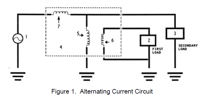
Figure l. illustrates an alternating current circuit which includes a typical commercial public utility alternating current power source (1) and a first load (2) coupled to a transformer (4). The transformer is interposed between the alternating current power source and the loads. The primary winding (5) is wound upon a magnetically permeable soft iron core and connected to the power source. Current flow through the primary winding produces a magnetic flux in the direction indicated by the directional arrows for half the AC cycle. The secondary winding (6) is connected to the first load (2) and is wound upon the same core in the same direction as the primary winding (5). The secondary winding (6) produces magnetic flux in the core in the same first direction at the same moment in time indicated by the arrows. The third or return winding (7) is wound on the core in the opposite direction from the primary and secondary windings, as illustrated in Figure 1, and is connected to a secondary load (3).
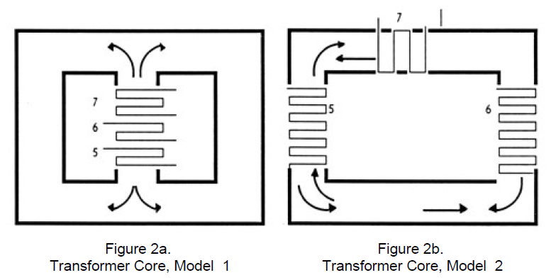
The third winding is wound on the same core as the first two windings (5 and 6) to produce magnetic flux opposite to that of the primary and secondary windings. Figure 2 illustrates alternative schemes for the windings on a magnetically permeable soft iron core. The direction of magnetic flux produced by the third winding (7) is indicated by the arrows.
Thus, an electric power conservation circuit has been constructed in which the magnetic fields of these windings are equal in absolute magnitude, i.e., the product of current times number of turns in each winding is equal in absolute magnitude. The sum of the magnetic fields of the primary and return windings is equal to the total magnetic field of the transformer.
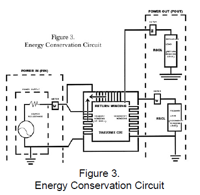
The transformer is ideally located between the main circuit breaker and the power distribution panel of a building. The secondary winding is connected to most of the secondary circuits terminating in the power distribution panel, but the third or return winding is connected to at least one of the secondary circuits. Preferably, the third winding is connected in line with the main power feed to all circuits. The public utility power lines are connected to the primary winding of the transformer. The flow of the alternating electrical current in the primary winding induces electrical current flow in both the secondary and third windings of the transformer to power the loads. (See Figure 3.)
The Technology
As in the past, when certain scientific theories have been accepted as fact, it is difficult for many scientists to accept that they have been wrong. Logically, this device goes against the tenets of current scientific theory since more power is generated from the device than was originally input from the original power source, that being the line feed from the electric company. The energy savings is accomplished by balancing the electrical fields thereby reducing the resistance to the flow of electricity. Thus, the new product does not really produce more electricity, but rather maximizes the efficiency of the electricity that is already present. It lowers resistance and maximizes other efficiencies to get the maximum power output with a minimum of electrical input. An illustration of the concept would be to use an analogy of two automobiles with identical engines and horsepower. If one has superior aerodynamic design, it will produce faster speeds. The end result is that the superior automobile gets more power output for the gasoline consumed or fuel input.
The presence of the opposing flux of the third winding acts to increase the impedance of the primary winding. This increased impedance results in a reduced current flow in the primary winding, thereby reducing the current drain from the public utility power supply lines. Since the current flow in the secondary winding is induced by the current flow in the primary winding, the secondary winding acts as a load with respect to the primary winding. The flux produced by the third winding reduces the impedance in the secondary winding, but does not reduce its output. Thus, the presence of the third winding on the transformer produces a magnetic field which decreases the energy input to the primary winding, but keeps the energy output to the secondary winding constant.
To produce an energy conversation circuit of high efficiency, the primary and secondary windings of a typical ETSL unit would consist of 120 turns of wire, while the third winding would have 50 turns of wire when the transformer is used with conventional 60 cycle power. Depending upon the number of turns and the load magnitudes the transformer unit can reduce the power consumption necessary to operate a given load producing savings from 13 to 25% as compared with conventional public utility power supply systems. The ideal conditions for maximum efficiency and minimum energy consumption are: (1) the magnetic fields of all three of the windings are to be equal in absolute magnitude; (2) for current times the number of turns in each winding to be equal in absolute magnitude; and (3) for the sum of the magnetic fields of the primary and the return windings to be equal to the total magnetic field.
Test Procedures and Results
A test was performed using the Energy Trimmer (ETSL-3) sized for a 40-100W secondary (fixed) load and a 0-1000W primary load. The test was performed to measure voltage, current and power of input, and the output. In each case a computation was made of the power factor and there was an examination of voltage and current waveforms of each. The environment required a fixed secondary load of 75 watts and a variable main load of 0, 300, 600, and 900 watts (rated). The Energy Trimmer was placed on 5 of the lighting circuits within an electrical panel which contained a total of 11 circuits.
The Energy Trimmer was connected to electrical loads which consisted of incandescent lamp banks connected to the main primary and secondary outputs. An adapter was used to connect volt-amp-wattmeter and oscilloscope at each location. The same wattmeter, was utilized for all measurements at each location to eliminate differences in metering affecting results. Waveforms at each location were examined to insure that harmonic content remained within the range of measurement accuracy of the meter. All measurements were made at fully stable conditions, with the unit fed from a regulated source of +/- 0.1% line voltage.
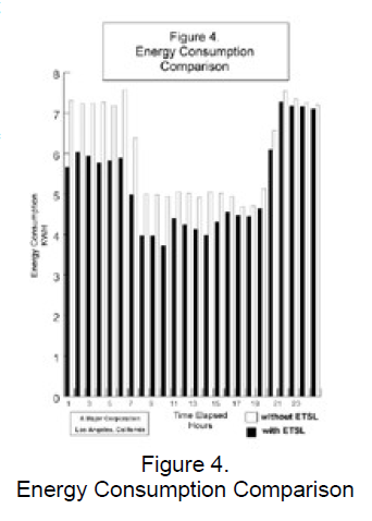
In one demonstration at the test site, two meters were used simultaneously to monitor the watts and volts. One monitored the input power and the other the power being dissipated in the loads. The results showed that only 1,013 watts and 494 volts were supplied from the main power source, while 1,343 watts and 292 volts were delivered to the loads. By deactivating only one of the return windings which would deactivate a part of the Energy Conservation Circuit, instead of requiring only 1013 watts, the system required 1247 watts of input power. When all the return windings were deactivated the system required 1,343 watts of input power. Thus, a savings averaging 300 watts was recorded which is approximately 19% savings in electricity costs in running the lights on the facility.
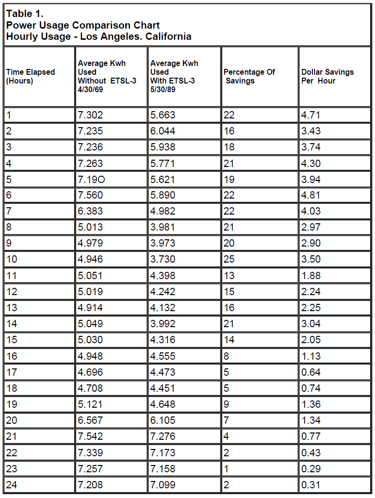
Savings up to 22% have been measured at peak operating times. (See Table 1 and Figure 4.) The variation of the main load from 0 to 1000 watts caused no apparent change in the secondary load, either in magnitude or waveform. It was noted that as the load increased, the harmonic content of the primary current decreased as the waveform shifted closer in phase to the primary voltage waveform so that the power factor improved with increasing load.
Both secondary and main loads were shown to draw a unity-power-factor current with loads that are resistive, whereby, the Energy Trimmer furnished a sine-wave to both primary and secondary loads. The result is a sinewave whose voltage and current are in-phase under all loading conditions. The waveforms of the feedback circuit also exhibited similar waveforms to the primary indicating that the ratio of feedback to input power is essentially constant.
With any appreciable load on the main load output, the harmonic distortion in the primary current is low, and consists mostly of the third harmonic. No EMI is visible in any of the waveforms, so the device should not cause any power system interference.
Conclusions
In short, a new advanced circuity is available for energy savings applied to commercial, industrial and residential use. It is a electrical control device which is attached behind the electrical meter but ahead of the electrical control panel. The basic concepts of the device will not be disclosed until more units are available in the field.
When the ETSL unit is activated--it decreases the use of energy being used in the home, factory or industrial site regardless of size of the installation or the power demands of the user. Undoubtedly, other variations and modifications will need to be made to accommodate the needs on the global level. There is, however, one important overriding consideration for all workstations and factories. The ETSL conservation circuit works within the energy grid system of the existing major power utilities and is not technology positioned against the utilities as some forms of alternate energy technology and cogeneration. It is completely safe and complementary to all energy utilities. Thus it is a benefit to both heavy industry as well as small users and does not interfere with environmental considerations already in place with major and minor energy users.
The result of 10 years of research and experimentation at several factory facilities in Los Angeles and utility substations throughout the State of California has shown engineering observers and company users that the more they use the system the more they save, and when more return windings are added to their facility further savings are realized. In fact, Southern California Edison has approved the installed ETSL units for its rebate program. Clearly, considering the growth of new industry, costs of expensive new designs in the work place, and the need to reduce the heavy power consumption in growing population areas, the ETSL units comes as a welcome addition to 21st Century technology.
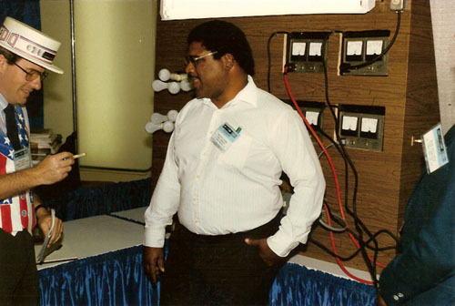
The following image if Melvin Cobb demonstrating his Energy Conservation Circuit. Please visit: Melvin Cobb
An Electrifying Idea : Inventor Is Determined to Prove Energy-Saving Gadget Works
October 16, 1993|BOB POOL | TIMES STAFF WRITER
For what must be the thousandth time, Melvin Cobb shrugs, takes a deep breath and starts talking about watts and volts and amperes.
The electrician from North Long Beach is discussing energy conservation. More specifically, he's trying to explain why he believes the device he invented can drastically reduce electricity needed to power a home.
Cobb gets to the part about secondary windings and magnetically permeable cores before he notices the blank look on his listener's face.
"The return coil creates a magnetic field that . . . ," he continues, groping for words that will make it all clear.
"I really don't know how to explain it," he finally admits. "You lower the resistance by canceling out the magnetic field. You use that in a transformer and you can lower the amount of energy going into the circuit while you maintain the output."
For nearly 15 years, the soft-spoken Cobb has been trying to tell why he thinks an electric coil can salvage energy that is normally lost when power company lines are hooked up to homes and businesses.
Power lines, in fact, gave him the idea. He was an Edison Co. employee in 1974 when he glanced up at a power pole at the corner of Orange Avenue and Wardlow Road in Long Beach. "Suddenly," he says, "a light bulb went on in my head."
What followed were years of trial-and-error tinkering with switches and copper wire in a cluttered spare room at his home on 69th Way.
"We'd be watching TV and suddenly hear this buzzzzzzap from back there and then we'd hear him say, 'Oh, well,' " remembers his wife, Beverly. "Sometimes the lights in the house would blink and then go out. It was like Frankenstein's lab."
Like most inventors certain they are on to something big, Cobb became obsessed. He refinanced his house to buy materials and equipment. At one point, he filed for bankruptcy.
He attached his first coil to his home's electrical system as a test in 1981. He was ecstatic when power usage plunged, just as he had hoped it would. But he was in for a jolt from his employer.
"I got a disciplinary letter from Edison, accusing me of stealing electricity," Cobb said. "I wasn't stealing. I was conserving." The complaint was later withdrawn.
Cobb patented his process in 1987, figuring the public utilities world would be electrified by his discovery. He was wrong.
He maintains he has never been able to get a full-blown test that would prove the usefulness of his invention--and prove that trickery isn't behind it.
Only a handful of people--mostly friends--have agreed to let Cobb connect demonstration units to their lines.
Most have been installed at homes, where before-and-after energy consumption comparisons are difficult. "I noticed a significant change in my electric bill--maybe about a 40% savings," guesses Dr. Ross Miller, a physician whose home was hooked up about five years ago.
Gauging conservation hasn't been much easier at the few institutional connections Cobb has managed to wrangle, either.
He installed one of his circuits four years ago at an American Honda Co. office in Torrance, where he was working at the time as a temporary employee. But after he left, officials promptly forgot about it. These days, no one can remember whether it worked--or even whether it's still plugged in.
Los Angeles officials agreed to evaluate the device last year after Cobb's uncle, retired realty title examiner Terry Cobb of West Los Angeles, appealed directly to Mayor Tom Bradley.
The test was conducted at the city's Mar Vista Public Library. But it was cut short because of a problem with the building's newly modified fluorescent lighting system.
Officials never figured out whether Cobb's coil caused the problem. But Sam Aloway, the electric technology adviser for the Los Angeles Department of General Services who tested the device, said it seemed to save energy.
"I was skeptical at first. His theory violated all reasoning," Aloway said. "Then I hooked it up and did readings and load calculations, checked to see if the wiring was heating up, checked to see if the meter was being fooled. Everything seemed to be working. It just may be a big breakthrough as far as the electrical industry is concerned."
Other engineering experts are more cautious. They suspect that Cobb conserves energy by reducing voltage--something that can damage sensitive equipment such as computers.
"I'd agree I'm a skeptic. But somebody can always discover something new," said city Department of Water and Power engineer Isaac Tasinga, a specialist in electromagnetism. "I wouldn't rule out anything."
Cobb's dogged quest took him last week to the University of Nevada Las Vegas, where he connected his 50-pound circuit to a bank of 100-watt light bulbs and a pair of watt meters in front of engineering students.