Become a member of our Forum, and gain access to a lot more information!


The MEG Replication Project by hyiq.org

Please Note: The MEG is a Patented Device. hyiq.org has been granted permission for this Replication by The MEG's Inventors.


Very early construction and some eager pre testing to see if I can see anything amazing. Being this is just an early setup I will not be posting to much information.

You can see my cores are very large and rather heavy. Working on cores this big with out popper Winding machines is a bit difficult. You can see below how big the cores actually are.

MEG Replication:

Within the magnetic world, the last measurement of a magnet is generally considered the measurement of which the direction of magnetism travels parallel through.

Magnet Type Height Length Width
Ferrite SrFe03 40mm 25mm 10mm

I have to be a little tricky here to make this work. I need to glue all ten Magnets together to create one Magnet with the right dimensions to fit inside the Window Area of the MEG's Core. This has to be a nice tight fit. The Magnetisation is through the 10mm Face, so the North Pole moves through the Magnet on the 25mm Face parallel with the 10mm Face to the South Pole to the other 25mm Face. I will need 4 Magnets high, to make the 40mm and 2 sets of these 3 Magnets long, giving me 120mm long, with all north poles in one direction and all south poles in the other direction. If I get a custom Magnet made I will be looking at minimum purchase restrictions and this is very expensive.

So here you can see all North Poles of the individual Magnets are facing up and South Poles are facing down. I have glued 3 sets of 4 magnets in each set together.

All North Poles must face in the same direction, this makes pushing the Magnets together a little difficult as they want to push away from each other. I used G-Clamps to hold the Magnets in place with an Alloy Right angle Plate to make sure they are straight and in line when gluing them.

The Core - Metglas® Alloy 2605SA1:


CORE # AMCC-1775
a
(mm)
33.0±1.0
b
(mm)
40.5±0.5
c
(mm)
106.30±1.25
d
(mm)
142.00±1.5
e*
(mm)
106.5±2.5
f*
(mm)
172.6+4.0
Lm*
(cm)
39.72
Ac*
(cm2)
39.36
Core
Wt.±2%
(gm)
11466.0
Window
Area
(cm2)
43.05


I got my cores from http://www.uaml.net/. The Contact there is Vikas. He is very helpful. Please mention Chris from hyiq.org and Vikas will help you out.


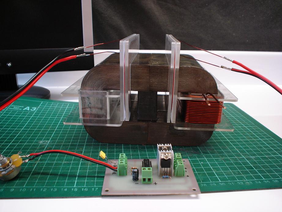
The MEG Driver Circuit:

Initially I will be using a variant of the MEG Circuit from Jean-Louis Naudin.

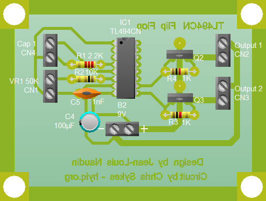
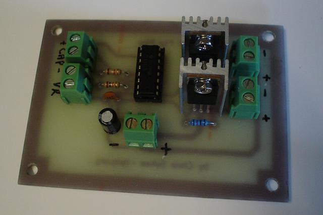
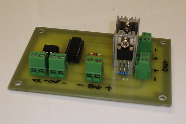
My replication of Jean-Louis Naudin's Circuit:

Click Here or on the Picture to download the Circuit Wizard Circuit File.

Download Circuit Wizard 30 Day Trial here.

Click Here for the TL494CN PWM Chip Datasheet.

Get your TL494CN's from Mouser Electronics.
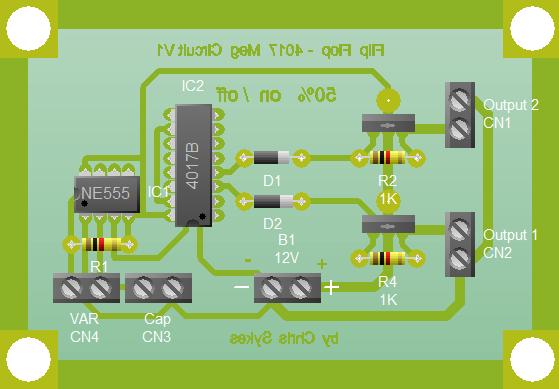
The J.L. Naudin circuit, above, is a 50% Duty Cycle, so the circuit has two channels, one channel is on 50% of the time then off the other 50%, the other Channel is 180 degrees out of phase, when channel one is on, channel 2 is off and vice versa.

Most likely I will be using another circuit to Drive the Actuator coils. This Circuit will be a basic Fett Switching circuit and more information will be posted soon about this.

I am also looking at a 25% duty cycle driver circuit. I am building the circuits modular for a few reasons. The main reason is that it makes it easier to change one small part of the circuit if I need to.

Click Here or on the Picture to download the Circuit Wizard Circuit File.


Above, in a 25% duty cycle circuit, again we have two channels, the Circuit is off 25% of the cycle, then channel one moves to an on state 25% of the cycle, then again the circuit goes into an off state 25% of the cycle, then channel two moves to an on state 25% of the cycle. Because 4 x 25% = 100% this is one full cycle. We can see here the circuit is actually off 50% of the full cycle.


Ref for Duty Cycle: http://en.wikipedia.org/wiki/Duty_cycle