|
Project
|
Update Description (HTML)
|
Update Content (HTML)
|
Date Created
|
Date Modified
|
|
|
Floyd "Sparky" Sweet - VTA Replication Project
|
Flux Gate Magnetometers or Magnetic Induction Compass.
|
|
|
Flux Gate Magnetometers or Magnetic Induction Compass.
Here we see a beautiful device. We see many variations and the best thing is that
they work by simply moving ElectroMagnetic Flux. They are also very simple devices.
Some pictures to give you an idea on the construction:
Parallel core magnetometers, Vacquier configuration shown on the left and Foster
configuration on the right:

Ring Core sensor developed jointly by the Naval Ordnance Laboratory and NASA Ames
Research Center:
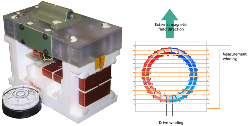

How a Fluxgate Works
Fluxgate sensors are typically ring cores of a highly magnetically permeable alloy
around which are wrapped two coil windings: the drive winding and the sense winding
(as shown in the figure). Some sensors will also have a third feedback winding,
if the sensor is to operate in closed loop.
It is helpful to think of the ring core as two separate half cores shown in blue
and green in the figure. This ring core is set up to measure the field in the direction
of Hext. As the current flows through the drive winding, one half core will generate
a field with a component in the same direction as Hext and the other will generate
a field with a component in the opposite direction as Hext.
DRIVE WAVEFORM
An example drive waveform is shown in Figure 2a.; The transitions are infact more
'square' than shown in the figure, here they are exaggerated to emphasize what is
happening in the 2 half cores.
No external field
In the absence of an external field (Hext= 0) the two half cores go into and come
out of saturation at the same time. The fields generated exactly cancel out as shown
in Figure 2b and there is no net change of flux in the sense winding, and hence
no voltage induced.
With external magnetic field
When there is an external field, the half core generating a field in the opposite
direction of the external field (for first transition in Figure 2c, shown in green)
comes out of saturation sooner and the half core in same sense as the external field
comes out of saturation later. During this time the fields do not cancel out and
there is a net change in flux in the sense winding (shown in black). According to
Faraday's law, this net change in flux induces a voltage, shown in black in figure
2d. Similarly towards the end of the transition, the half core now generating a
field in the same direction as Hext goes into saturation sooner. Consequently, there
are two spikes in voltage for each transition in the drive and the induced voltage
is at twice the drive frequency.
Measuring the field
The size and phase of the induced spikes tells us about the magnitude and direction
of the external field. To help amplify this signal to make it easier to detect,
the fluxgate magnetometers produced by Imperial College use a capacitor to tune
the sense winding. The tuned sensor waveform is shown in red in Figure 2d.
Ref:
Imperial College
Now lets have a look at our geometries and see if we can see any similarities:


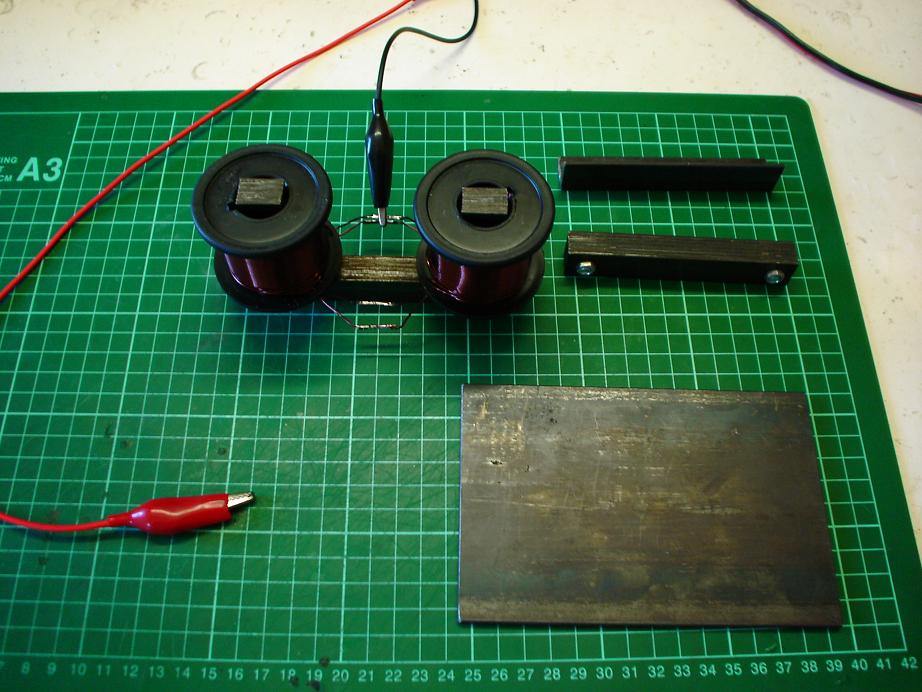
Certainly we can see some similarity's here, and maybe the actual operational characteristics
are similar to?
|
|
|
1/09/2009 2:29:36 AM
|
10/10/2013 2:29:36 AM
|

|
Edit |
Details |
Delete
|
|
Floyd "Sparky" Sweet - VTA Replication Project
|
Was the VTA really started by connecting a Battery to a few terminals? We find that there was good evidence for this.
|
|
|
HI Everyone,
Some evidence of the starting of the VTA by a Battery
here which supports the Schematics in my last update. Most of you would have read
this before. If not then you will find this a good read. Thanks Mr Rosenthal.
Floyd Sweet's VTA Unit
by
Walt Rosenthal
(Excerpted from: Space Energy Newsletter
IV (1) March 13, 1993 ~ PO Box 11422, Clearwater, FL 34616)
The Vacuum Triode Amplifier (VTA)
invented by Floyd Sweet consists of two ferrite magnets and two to four coreless
wire coils. It is self-powered in the preferred configuration and produces in excess
of one KW of 120 VRMS 60 HZ power in the form of energy that resembles electricity.
This energy is referred to as negative energy. The VTA development history, its
anti-gravity characteristics, negative energy properties, and some of the personalities
involved are discussed.
This is a story of Floyd Sweet's trials
and tribulations involving a mystery wrapped in an enigma. God revealed to Floyd
sufficient information to build a machine to provide energy that resembles electricity.
However, God did not provide solutions to the frustrating string of problems that
would surface in converting the idea into a working device. There are several people
in this story that have provided help and some who have hindered.
When Tom Bearden met Floyd, the device
Floyd had developed was producing a few watts of alternating current at 28 volts.
Tom saw in Floyd's device the physical embodiment of a principle he had theorized
many years before. Tom had never designed or constructed a physical device
to access this elusive energy source.
Tom's name for the extraction process
is 'Four Wave Phase Conjugate Mixing'. The energy source is the intense non-cohered
energy that is thought to be present everywhere in the universe. Various researchers
through the years have given this energy different names, such as "Zero Point
Energy", "Gravity Field Energy", "Radiant Energy", and
others.
Tom Bearden gave Floyd's device the
name "Vacuum Triode Amplifier" or VTA. The machine provides a small amount
of its output fed back to the equivalent of a grid which gates or coheres a large
amount of energy which appears at the device output terminal as something that resembles
electricity! Negative Electricity.
This energy can be utilized by devices
designed to convert electricity to light, heat, or mechanical work or anything else
for which normal electricity is used. The properties of this energy, although superficially
resembling the 120 VRMS 60 HZ power we normally use, are unique and sufficiently
different from conventional electricity, so that it should be classified as an entirely
new energy form. It will require careful extended study by a wide range of people
in order to document its properties in the manner scientists have done with conventional
electricity.
Tom Bearden refers to this energy
as negative energy, and he states that negative time must be utilized. In negative
time according to Bearden, gravity is a repulsive force.
Floyd's experiments demonstrated that
the VTA loses weight in proportion to the amount of generated "Negative Energy".
This was carefully documented by Floyd on a kitchen scale. The machine weight was
observed decreasing with increased load in a quite orderly fashion until a point
was suddenly reached when Floyd heard an immense sound, as if he were at the center
of a giant whirlwind but without actual air movement. The sound was heard by his
wife Rose in another room of their apartment and was heard by others outside the
apartment. The experience was very frightening and the experiment has not
been repeated.
Some observers of the light emanating
from ordinary 120 volt 100 watt incandescent bulbs powered by the VTA claim the
light is different, softer than normal incandescent light. The VTA magnets and coils
when powering loads of over a kilowatt become cold and temperatures of 20 degrees
F below ambient have been observed. Similar reports of below ambient temperature
of energy machine components have been reported by other inventors, such as John
Bedini and John R.R. Searl.
When the VTA output wires had been
accidentally shorted, first an extremely brilliant flash occurred. When the wires
involved were examined shortly afterward, they were found covered with frost. Unfortunately
this also caused the VTA magnet to fracture and the machine ceased operating. In
one instance the machine operation ceased during a local earthquake. The physical
shacking was not believed to be sufficiently severe to disrupt the machine magnet/coil
relative placement or physical shock to the magnet such as a hammer blow might impart.
The best speculation is that the machine was affected by the intense electromagnetic
pulse known to originate from earthquakes.
Conventional instruments used to measure
volts, amps, or watts appear to correlate machine output as coupled to loads, but
only up to approximately 1 KW; above that value they may indicate zero or some other
value not related to the known actual load.
Floyd's attempts to use conventional
electrical design formulas relating number of coil turns, amp turns on drive coils,
and any other parameter to predict observed outputs have all resulted in failures
with calculations. Empirical formulas based on actual tests have been documented.
Observation of machine output voltage
of approximately 120 VRMS while the load was changed in 100 watt increments from
100 watts to 1000 watts has shown no observable output voltage change, which suggests
an extremely low internal equivalent impedance. The 20 gauge magnet wire in the
output coils consisting of several hundred turns has significant DC resistance which
is not correlated with the unvarying output terminal voltage at different loads.
It is speculated that this energy does not travel within the copper wire or its
passage through the copper wire does not generate a voltage drop --- a most useful
feature when transferring energy from one place to another.
One frustrating aspect of the VTA
has been its failures, evidenced by the output voltage slowly decaying to zero over
a few seconds or minutes. There also have been spontaneous instances of the voltage
rising above 120 VRMS as observed by the increased lamp load bank brightness. The
volt meters, ammeter, and power meter did not correlate with the brightness change
except when the machine would the fail to produce any power.
Many times the VTA was normally left
on powering a lamp load bank 24 hours a day. During a period of time when it appeared
to be functioning properly all day long, Floyd got up at 3:00 AM to go to the bathroom.
As he walked past the room where the VTA was located, he noticed that the lights
appeared dim. He measured the voltage at 70 VRMS. Being tired at the moment, he
returned to bed. The next morning when he rose, the voltage was back to the
normal 120 VRMS and stayed there all day. The next night Floyd got up at 4:30 AM.
The voltage was measured at 85 VRMS. Floyd returned to bed. The voltage was normal
the entire next day.
A possible clue to this anomaly has
appeared in an article by E.W. Silvertooth titled 'Motion Through The Ether' where
Silver tooth describes a dual path laser interferometer experiment that conclusively
demonstrated the presence of an ether that flows through our portion of the universe
at greater than the speed of light with its vector in the direction of the constellation
Leo. Floyd's VTA may be orientation sensitive to this ether velocity vector.
The VTA consists of two 4" X
6" X .5" grade 5 or grade 8 ferrite magnets spaced 3 inches apart in the
attractive orientation, with the output and drive coils in between. The output coils
are wound with 20 gage magnet wire. Their axis is parallel to the magnetic lines
of force between the two magnets. The two drive (or excitation) coil axes are positioned
at 90 degrees to the output coil axis. The VTA excitation coils may be driven by
the VTA output voltage or a separate sinewave oscillator source.
The "Secret" to the machine
is the process that "conditions" the magnets. This conditioning process
determines the output frequency and also prepares the machine for operation.
The same machine could be just as well "told" to output 50 HZ or 400
HZ. The conditioning technique is so novel, it is doubtful anyone would ever guess
how it is done.
Oscilloscope observation of the VTA
output voltage waveform shows an apparently perfect sinewave that is not phase locked
to the local 60 HZ powerline voltage.
The VTA can be started by momentary
connection of a 9-volt battery to the drive coils when the machine is operated in
the self-powered mode. The operation is stopped by momentary interruption of power
to the power coils.
The VTA "likes" to always
see a minimum load of 25 watts.
Electrical shock to humans from the
VTA may be more damaging than contact with a 120 VRMS 60 HZ conventional powerline
voltage. Floyd has accidentally had VTA current pass from his thumb to his
smallest finger. It appears to freeze the flesh and was extremely painful for at
least two weeks.
The mechanism by which negative energy
makes copper conductors cold but will also heat light bulb filaments is not understood.
Tom Bearden has coined the term "Gravito-Striction" for this process and
has described how he believes it works.
On the human side of the VTA development,
some incidents are worth telling. Two people from Australia, who claimed they wanted
to help Floyd, stole his notebook and promptly asked John Bedini for help in replicating
the VTA based on the notebook contents. John recognized the notebook as belonging
to Floyd and promptly asked them to leave. However, the notebook was never recovered.
Floyd has received many death threats
over the phone, and some threats face to face. A well dressed gentleman in an expensive
suit, tie, hat, and hundred dollar shoes approached Floyd on the sidewalk of the
street where he lives and introduced himself as Cecil Brown. He showed him a picture
of Floyd inside his apartment. Cecil then told him that he represented a conglomerate
that did not want Floyd's device to appear in the world at this time. He further
stated that sometimes unfortunate things happen to people who do not comply with
the wishes of others. He then retrieved the picture and departed. Incidences like
this do impart significant concern in Floyd's mind!
One real unsung hero of the human
side of this story is Al Margolin, who for many years has provided test equipment,
fabrication help, and transportation for Floyd and Rose whenever needed, and it
was needed many times.
Floyd's long time friend and former
employer Bill Lawry has provided living and project expenses and fabrication help
when needed.
The reliable conditioning of the magnets
in a manner that assures long time operation is the Achilles heel of this device.
With the help of enough of the right people this device may change our world and
open a new field of physics! This adventure of course is an on going and the final
goal of powering the world with the VTA is still a long ways off.
I just want to underline the paragraph:
The VTA can be started
by momentary connection of a 9-volt battery to the drive coils when the machine
is operated in the self-powered mode. The operation is stopped by momentary interruption
of power to the power coils.
The VTA "likes" to
always see a minimum load of 25 watts. "
Now this information begs some serious questions.
How could the Magnets if they were conditioned and had permanently moving flux possibly
be stopped by the momentary interruption of power to the power coils? Or even started
by a 9volt battery. I do believe the above information to be true. I believe that
the MEANING of the conditioning has been miss understood and the conditioning is,
like I said in my last update, the "Starting of the SQM/VTA". The SQM/VTA
must be assembled and complete to be able to sustain itself. A signal of 60Hz can
be used to start the SQM/VTA or 400Hz like what has been said in the past documents.
In all my research there is one thing I did find out
and it has been cleared up for me. The Notebook mentioned above. Some of the people
funding Floyd were sceptical of the SQM/VTA at the time and wanted proof of concept
and the Notebook was taken for reproduction of the SQM/VTA by another researcher
at the time to replicate the SQM/VTA. I have been told the Notebook was returned
to the people who supplied the notebook, being Floyds Funders. I have emitted names
and locations but Australia was not involved in the Notebook incident at all. I
know at least one person (Funding Floyd Sweet at the time (1984-1986)) must have
some seriously good information on the SQM/VTA and living in the United States with
this information would be a matter of National Security? Would it not... Maybe Human
Survival is a bit more important?
So download my pages and share them, share this to
everyone and do not forget it. This technology must not be patented and stopped
from becoming public domain. It is not about the money, yeah I have heard that before...
Well more coming soon as always.
@ViewBag.MessageHeader
@ViewBag.Message
|
|
|
2/01/2008 2:34:49 AM
|
10/10/2013 2:34:49 AM
|

|
Edit |
Details |
Delete
|
|
Floyd "Sparky" Sweet - VTA Replication Project
|
Now is the right time to share more experiments. I have decided an old video I took nearly two years back would be of value to others. Here I show how to build and tune a Solid State Generator. The Globe is rated at 12V 300ma (3.6 Watt). Input is 1 Watt (5V 200ma) I am getting slightly more Output than this. This Generator is Lenz-Less. Its free from Lenz Law restrictions.
|
This is an old video I made some time back. I have
decided that it would be valuable to others:
Note: This Globe is a 12V, 300ma (3.6 Watt) Globe. I
am getting very good illumination for 1 Watt (5v * 200ma).
The visual evidence surely speaks for itself here.
Related Document's:
Magnetic Resonance by Floyd A. Sweet. PH. D:
Click Here
Gennady Markov - Bi-Directional Current Transformer:
Click Here
Gennady Markov - Bi-Directional Current Transformer: Patent CA2224708
Click Here
Perhaps one of the most important documents of all: Guidelines to Bucking Coils:
Click Here
Others are showing devices that use the same working principals. One good
example is Bill Alec:
Tom Bearden has been telling us for years what Floyd Sweet did. One just has
to get past the fact that Floyd Sweet did not "Condition" his Magnets. Magnets
amplify the effects I have shown.
"Now to some specific issues: Yes, my insight did keep growing. At first I
took the results of experiments such as by Hooper, with opposing "ordinary
waves". The effects of the core for the coils were a puzzle, but it seemed that
sometimes the "opposing normal waves" would give some G effects, and more often
they would not. What I did not realize for some time was that the longitudinal
wave can be regarded as a superposed wave/antiwave, via a single SWZ wavepair.
This agreed with Whittaker, and also now offered a sudden inspiration as to when
we got the G effect and when not.
We were dealing with four waves, not two, in the opposing ordinary waves. We had
two opposing normal waves and two opposing antiwaves, with the wave/antiwave
coupling. Two ordinary waves 180 degrees out of phase would certainly cancel
(spatially) their amplitudes (as is well-known in RAM materials and structures)
but would not cancel their energies. The two antiwaves would do likewise,
spatially. The point then became, so what would happen in the time domain? Here
we got a shocker. The two antiwaves would cancel each other's amplitude
SPATIALLY, and would add energies. But looking at the action (energy x time)
aspect, their energies exist in negative time!
Well, this meant that the antiwave ACTION would come out negative, and would
then cancel the added positive wave ACTION because ? Ewt + ? Eaw(-t) = 0.
Therefore the sum of the whole mess was zero! Bummer! We wound up with
everything just vanishing, wherein all the action (angular momentum) seemed to
vanish. Well, this showed that the notion of simply having waves 180 degrees out
of phase of itself would not give gravity effects. So that's why mostly the
Hooper approach didn't seem to do much. But if one added nonlinear materials to
the core, then one broke the linear cancellation. Once in a while, if one got it
just right, one could get some spooky gravitational effects. So that was a real
clue."
Ref: http://www.cheniere.org/correspondence/072796.htm
"( 6 ) Investigative experiments to explore bucking EM force fields which neatly
zero sum would have almost immediately revealed highly anomalous behavior of
materials and circuits. [Such simple investigations of zero-vector EM force
field summation do not seem to appear in the Western literature at all, so far
as can yet be established.]***
***with the single exception of the Aharonov-Bohm effect, which has finally been
proved after 27 years of controversy, and Hooper's work which was obscurely
published.
Something very much like that, together with quantum mechanical ideas, would
have had to be applied to explain the operation of the Moray device. Note that
every one of the suppositions above was available to any thorough Soviet
search—and the Soviet scientists certainly made the search, more massively and
thoroughly than has ever been done before or since. Since the evidence is
overwhelming that the Soviet scientists developed electrogravitation and scalar
EM weapons, it seems logical that their search succeeded along these lines or
similarly."
Ref: http://www.cheniere.org/books/analysis/history.htm
"I'd also like to point out the patents and work of Hooper. Hooper seems to be
the only physicist who ever methodically investigated EM stresses, structuring
of those stresses, and the gravitational implications of those stresses in the
laboratory."
Ref: http://www.cheniere.org/misc/interview1991.htm
Don't be a DUMMY!!! Learn this technology and experiment with
this now, before its too late!!!
|
3/11/2014 9:05:50 AM
|
7/11/2014 8:37:50 AM
|

|
Edit |
Details |
Delete
|
|
Floyd "Sparky" Sweet - VTA Replication Project
|
Dale is a member of the hyiq effort to replicate the SQM and has posted in the forums an amazing effort of putting together all the scientific references and more information of the internal working of the Atom with diagrams of the way it all works. Excellent Job Dale
|
|
Hi Everyone, Dale is a member of the
hyiq effort to replicate the SQM and has posted in the forums an amazing effort
of putting together all the scientific references and more information of the internal
working of the Atom with diagrams of the way it all works. Dale you have done a
brilliant job here mate. Excellent Job Dale, Thank you.
Part 1
Hello
everybody,
Yep, when you think about it, a 'modification' is
anything that's not factory. They were making a movie and of course
would naturally want it to sound as complicated as possible, more scientific.
Ok, initially this looks like a repeat of the same stuff. However, there are other
effects that result from different perspectives. These will be added in as it goes
along. I find that the naming conventions that were applied so many years ago to
the electron and the photon automatically restrict our thinking processes.
I hope to be able to conceptualize two types of SQM to everyone by the time I'm
done. Yeah..... two differently constructed units that do the same thing using the
same principals.
: Synergy....the whole is greater than the sum of the parts...
(remember..., an electron inside an atom is the same
electron(s) powering your computer. We already use the 'stuff ' of atoms
all the time in common everyday items.)
http://encyclopedia.thefreedictionary.com
is the source for orange
colored text.
Anything from Bearden will be
red and Floyd will be
green.
In physics, an
electric field or E-field is an effect produced by
an electric charge that exerts a force on charged objects in its vicinity.
~ It doesn't matter what the object is as long as it's
got a charge and they're close enough. (I haven't found anything contrary
to that) So the E-field is an effect... the result of an electric charge's force
on an object that has a charge of it's own.~
Electric fields
are composed of photons and contain electrical energy with energy density
proportional to the square of the field intensity.
~Therefore, electric fields are are composed of electromagnetic
radiation since that's what photons are.
Note that this is a dynamic case statement. Also note that photons are
in motion at the speed of light by definition and therefore the electric and magnetic
fields are coupled by default, as long as there is motion.~
In the static case,
an electric field is composed of virtual photons being exchanged by the charged
particle(s) creating the field.
~No motion of electric charge = no magnetic field and only virtual
photons. This is all happening inside the 'orbits' of the electrons. This
is the very essence of the doorway to the vacuum and it's energy.~
In the dynamic case the electric field is accompanied by
a magnetic field, by a flow of energy, and by real photons.
~All of that from an electric charge that's moving AND exerting
a force on another charged object. Seems too simple doesn't it? We have to remember
that absolutely everything is in contact with the Virtual Vacuum, from the grand
scale of the Universe down to sub subatomic particles. Sometimes it's easier
to visualize it as a fluid. We are immersed in the Virtual Vacuum. Motion disturbes
this fluid. A certain kind of motion creates a certain kind of .... eddy current,
so to speak.~
In the description of the interaction between elementary
particles in quantum field theory, a virtual particle is a
temporary elementary particle, used
to describe an intermediate stage in the interaction.
~We're not dealing with 'static' electric charges.
Our electric charges are always moving. Always interacting because the electron
is always moving. The waterfall analogy.~
~For these Bearden references,
http://www.cheniere.org/techpapers/vanflandern.htm~
....As Nobelist Weinberg {} points out:
"… free electrons as well as electrons in atoms are always emitting and absorbing
photons that affect the electron's mass and electric charge, and so the bare
mass and charge are not the same as the measured electron mass and charge that are
listed in tables of elementary particles. In fact, in order to account for the observed
values (which of course are finite) of the mass and charge of the electron, the
bare mass and charge must themselves be infinite. The total energy of the atom is
thus the sum of two terms, both infinite: the bare energy that is infinite because
it depends on the infinite bare mass and charge, and the energy shift calculated
by Oppenheimer that is infinite because it receives contributions from virtual photons
of unlimited energy."....
~A charge is not always the same value. It changes all the time.
Virtual photons are being adsorbed and emitted all of the time.~
~ Bearden himself,~
.....After a year of searching some intricate things that did
not work, the solution to the desired negative entropy (coherent integration of
virtual state disorder into macroscopic observable state order) turned out to be
surprising simple. First, the receipt of "virtual
EM energy" by the source charge is primarily via its absorption of virtual
photons. Mass m of the absorbing charge q is unitary, and its absorption
of a virtual photon thereby constitutes the production of a differential dm of mass,
yielding (m + dm). As successive virtual photons are absorbed, we have m(t) = m0
+ dm1 + dm2 + ... + dmi + ... and so on. In
short, the differential unitary mass of the charge is steadily and coherently increasing
in its virtual state toward the observable state. This mass-energy change
becomes increasingly unstable (excited), from the virtual state viewpoint, as it
nears the quantum level and the observable state threshold.
When this increasing total dm reaches sufficient magnitude to constitute the energy
DE of an observable photon (DEDt) via DE = c2dm, the zitterbewegung (constant fierce
bombardment of the charge by virtual particles) simply triggers the abrupt decay
of the excited state and release of the excitation energy. This results in the radial
emission of an observable photon from the charge, at light speed outward into surrounding
space.
The "virtual photon absorption and unitary differential mass integration and
summation" is the long-sought coherent integration process. The zitterbewegung
plays the role of forcing the abrupt decay and quantum change that produce the observable
photon emission. The process repeats over and
over at incredible speed, in all directions, and this finishes the complete mechanism
by which the source charge continuously absorbs and coherently integrates virtual
energy from its seething vacuum exchange, and re-emits the integrated energy as
real, observable photons traveling outwards at light speed.
The result completes the full mechanism by which the source charge produces and
continuously maintains (at light speed) its associated "static" EM fields
and potentials. Also, it is a mechanism that conserves energy during the process.....
~Simple.... once a paradigm is removed from the brain.~
....The practitioners feed oscillating field energy into the
particulate medium wherein the medium’s particles are self-resonant at the input
energy frequency. In that case, the reaction cross section of course dramatically
increases. But that is also an increase in calculated or measured output divided
by calculated or measured operator input. It therefore represents a change in the
thermodynamic COP of the process itself (which includes both absorption and re-emission).....
....The ordinary vector divergence of the curl
is zero in a flat spacetime, but it is
not necessarily zero in a curved spacetime.The
self-oscillating particles of the medium do provide sufficient
spacetime curvature to allow some of the normal divergence-free Heaviside component
to be diverged anyway, thus furnishing an extra Poynting energy flow input (diverged)
component.....
~Here the self-oscillating part is a bit mis-leading. It is caused
by the oscillating field energy put into it in the previous paragraph. In any case,
spacetime is distorted, or curved, by the motion of the masses and charges involved.
The 'particles of the medium' being the mass. We've all seen the educational
film where a net is stretched tight and a ball is rolled around on it. The mass
of the ball is sufficient to curve the plane of the net. If the ball isn't being
moved around, meaning the curvature is stationary, it's area remains constant
per unit time. However if the ball is in motion, the area of curvature is greater
per unit time. The greater the mass, the greater the curvature. In the net example,
a steeper gradient is the result of more mass. Thus it follows that heavier elements
make stronger magnets.~
~Floyd (N is S),~
As postulated by Einstein in his famous equation E=MC^2 ,
energy is a kind of matter. So even the energy of distant starlight must be accounted
for in any holistic view of physical reality. The vacuum itself is literally popping
with virtual particles that appear and disappear in the field during instants too
brief to be measured. Virtual particles with lifetimes or dwelltimes too short for
the name "particles" to be appropriate.
As a result the generated fields are always in some state of flux. However,
under the influence of a generated Motional
Electromagnetic field parts of the normally chaotic virtual field break
off from randomness and form a more coherent region. This region consists of a structured portion of the spacetime continuum
which by its very nature seems to attract more virtual particles (This increase
in particle density has been verified by lab experiments conducted the week of June
19, 1988). This higher concentration of particles
develops a warping of the spacetime continuum where negative energy is
produced in abundance. The existence of this condition via direct engineering of
the virtual state allows for the safe generation of electrical energy. This condition,
in essence, forms the underlying principle of operation of the Phase-Conjugated
Vacuum Triode.
~ Curved spacetime that is....I see it as an extermely distorted
Gravity Well shape we are all so familiar with. It's shape (geometry) attracts
more virtual particles. Notice that Floyd said a Motional Electromagnetic field?
Not a motional E-field. We have become overly focused on 1/2 of the total field.......~
~Floyd (N is S),~
THE MOTIONAL E-FIELD
Of all the known fields- electric, magnetic, gravitational and motional E-field-
the only ones incapable of being shielded are the induced motional E-field and the
gravitational field. The nature of the motionally induced electric field is quite
unique; in order understand it more fully we must start by parting with a few misleading
paradigms. When magnetic flux is moved perpendicularly across a conductor an electromotive
force (e.m.f.) is electromagnetically induced ``within'' the conductor.
``Within'' is an artifact of the commonly used analogy comparing the flow
of electric current within a wire to the flow of water within a pipe. This is a
most misleading model theoretically. The true
phenomenon taking place has little been thought of as involving the production of
a spatially distributed electric field. We can see that the model's
origins likely arose from the operation called ``flux cutting'', a most
deceiving and misleading term. A better term,
``time varying flux modulation'', does not imply any separation
of lines of flux. Truly, lines of flux are always in closure upon themselves and
are mathematically expressed as line integrals. It is fallacious to use the term
``cutting'', which implies time varying separation
which does not in fact ever occur. .....A motionally induced E-field
is actually created within the space occupied
by the moving magnetic flux described above. This field is present therein,
whether or not a conductor is present in the space......
~The first part of this paragraph is very distracting. Floyd even
says so. So the end result is the Electromagnetic field actually. A Motional Electromagnetic
field. The electric and magnetic fields are NEVER separated. The bifilar coil is
going to double the electric field and cancel out the magnetic field. With it's
self-inductance being zero, no standard electricity can be induced as, by design,
there is no magnetic field allowed.~
~Ok, here's the Paradigm. "The electron is a negative charge." Nope,
that's not correct.~
The electron is a fundamental subatomic particle which carries a negative electric charge.
The electron is one of a class of subatomic particles called leptons which are believed
to be fundamental particles.
Electric charge is a fundamental conserved
property of some subatomic particles, which determines their electromagnetic
interactions.
Electromagnetic interactions are long range
attractions or repulsions between any particles or antiparticles that have charge.
If the particles are attracted they stay together,
because there is a continual exchange of photons.
~(Side thought--I wonder if this may be a part of the attraction/repulsion
mechanism?)~
~Electric charge is a property of the electron, just as Visible is a property of
a Form. ( Form1.Visible=True....) The electron is not the charge. The amount of
the charge/mass is not fixed. Quite the contrary, it's always changing due to
the influx of virtual photons and subsequent emission of real photons.~
In physics, a magnetic field is an entity produced by moving electric charges (electric currents)
that exerts a force on other moving charges. (The
quantum-mechanical spin of a particle produces magnetic fields and is
acted on by them as though it were a current;
this accounts for the fields produced by "permanent" ferromagnets.) A
magnetic field is a vector field: it associates with every point in space a (pseudo-)vector
that may vary in time. The direction of the field is the equilibrium direction of
a compass needle placed in the field.
~So we have a moving electric charge (current) producing a magnetic
field AND we also have Spin producing a magnetic field. Therefore, Spin is equivalent
to a moving electric charge (current). Since Spin and Charge are both properties
of an electron it would seem that there are two, or more, sources of magnetic field
from an atom. This may be the reason for the vortex nature of the lines of flux.~
~Since the magnetic field is a vector field, it cannot exist without either a moving
electric charge or non-cancelling Spins in an atom. The electric field is also a
vector field and cannot exist without an electric charge exerting a force on another
charged object. The electric field exists within the magnetic field. Or rather,
the magnetic field is created around the electric field when the electric charge
is in motion.~
Alright then. This a good place to end Part I. I have a complete train of thought,
but it's too long to do all at once. I think I have a solid grip on the sub
atomic picture. To convey it with a lot of details will just take some time. I'm
guessing two or three more like this one.
Well, have a good day everybody. It's time to find some aspirin... Dale
Part 2
Hello
everybody,
Sorry it's taking me so long to get through this. I don't have a lot of
free time.
I hope to wipe out another Paradigm today. The Sinewave.
Ok then, from Part 1
~So we have a moving electric charge (current) producing a
magnetic field AND we also have Spin producing a magnetic field. Therefore, Spin
is equivalent to a moving electric charge (current). Since Spin and Charge are both
properties of an electron it would seem that there are two, or more, sources of
magnetic field from an atom. This may be the reason for the vortex nature of the
lines of flux.~
~Since the magnetic field is a vector field, it cannot exist without either a moving
electric charge or non-cancelling Spins in an atom. The electric field is also a
vector field and cannot exist without an electric charge exerting a force on another
charged object. The electric field exists within the magnetic field. Or rather,
the magnetic field is created around the electric field when the electric charge
is in motion.~
http://encyclopedia.thefreedictionary.com
is the source for orange
colored text.
Anything from Bearden will be
red and Floyd will be
green.
Part 2>
~Lets go back to being 'immersed' in the virtual vacuum.~
/electromagnetic+field
If electric fluid starts to accelerate in a certain direction, it will cause a vortex
of magnetic fluid to move in circles around the direction in which the electric
fluid is accelerating (according to the right hand rule). As soon as the electric
fluid stops accelerating, the vortex of magnetic fluid vanishes.
~No motion of charge (no current) = no magnetic field, from that
source at least. The magnetic field is always the result of a moving charge (current).
Or the result of Spin which is equivalent to current.~
Notice that electric fluid will not accelerate spontaneously;
something has to force it to accelerate. This same thing then indirectly causes
the magnetic vortex to be stirred up: a magnetic vortex will not arise spontaneously.
Finally, if magnetic fluid accelerates in a certain direction, it causes electric
fluid to move in a vortex which circles around the direction of acceleration in
the direction opposite to the right hand rule.
To summarise, an acceleration of the electric fluid causes a positive vortex of
magnetic "liquid" to move around it, but an acceleration of the magnetic
liquid causes a negative vortex of electric liquid to flow around it.
~So the electric 'fluid' is structured by the left hand.
I think the positive and negative vortex's here refer to the direction of rotation
of the 'fluids' around the direction of propagation. Right handed being
positive by default. Thus the drawings below. These are 90' out of phase with
each other. In the orthogonal representations you see the standard sine waves. The
vortex nature is easy to see here. However this is only the local vortex around
the charge carrying electrons path ('orbit'). /circular+polarization.~
(This is the best substitute drawing I could find.
The electric field.)

~Below I've taken the orthogonal views from the merged fields
view above and merged them to occupy the same space. If you move your eyes up and
down the left image, you can see two ribbons counter-rotating. Note that each ribbon
is composed of two sine waves, one from the magnetic field and one from the electric
field, to make the image of the ribbon.~
(I couldn't figure how to put my drawing in here...)
~If the electron had a stable circular orbit around the nucleus,
the shape of these fields would describe a torus.~

~Of course this Torus isn't really correct either. The fields
established around the electron are local to the electron, (the charge on the electron
that is), so it would look more like the model of an atom that Chris has in the
Theory Update on 29-12-05 but without the trailing tail. Then too, there's more
than one 'producing' electron in the atoms we are using in the magnets.
The un-paired electrons. The whole thing ends up looking like a many stranded rope.~
~Those are the fields generated by a moving electric charge, being carried by the
electron. (This charge is exerting a force on another charged object. There has
to be another charged object nearby or there isn't an electric field. It's
easy to forget about the 'other charged object')
The repeating theme here is the vortex nature of the fields. We've had the Sinewave
stuffed in our faces for so long that we've forgotten it's not correct.
From Beardens site.~
(couldn't find it again on his site...)
~Electric and magnetic fields aren't flat as a sinewave implys.
The sinewave image interferes with understanding.~
~Electric and magnetic fields, it turns out, are not little 'butterflies'
flitting to and fro. Then neither are photons! Seems that the fields are more like
a propeller in the water. We don't see the water as much as we see the cavatation
caused by the motion of the propeller. We are immersed in the virtual vacuum.
~We can't forget about the Spin creating it's magnetic
field either.
http://www.cheniere.org/books/part4/index.html is a very good
read. Here are two of the graphic's from it,

There are a couple more that demonstrate this interaction. I was
very pleased to find these graphic's. Trying to get a good visual from the math
by itself is a real task.

According to Bearden, it's the spin that's hooking the
electron to the virtual vacuum. As of yet I don't have a physical representation
of what the Spin magnetic field looks like. I don't think it's going to
have the same shape as the field from a moving charge.
~Here we go again.~
~PHOTONS ARE NOT LIGHT. THEY ARE ELECTROMAGNETIC RADIATION, for our purposes. I
have to constantly remind myself of this.~
....Creation
Photons are produced by atoms when a bound
electron moves from one orbital to another orbital with less (more negative) energy.
Photons can also be emitted by an unstable nucleus when it undergoes some types
of nuclear decay. Furthermore, photons are
produced whenever charged particles are accelerated.
~The first underline relates directly to the second drawing from
Bearden. The second underline tends to be ignored I think. The first thought is
a big linear accelerator. However, acceleration is induced motion in a direction.
We're not going to make the electron go any faster than it is. But we can give
it some acceleration by making it's path change with the exciter coil. Motion
in a direction.
What we are trying to do depends on the MOTIONAL effects of charges and fields.
A standard generator is moving magnetic fields across conductors. It used to be
that magnetos were the standard. They used actual magnets instead of creating a
magnetic field by current flow through a coil. This is relative motion between the
components and will only generate standard electricity.~
Floyd(N is S)
In the application of the presented equations it is required
that one refer all flux densities
and movements to a single specified coordinate system. In particular, the velocities
will all be
with respect to this system alone and not interpreted as relative velocities between
conductors or
moving lines of flux. The coordinate system is arbitrarily selected and the magnitudes
of
variational and motional fields depend upon the selection.
~In the SQM the magnets and the coils are stationary. We have
no relative motion between them. The motion of the flux was induced by the exciter
coil. Lets restate the last sentence.~
The magnitudes of variational and motional fields depend
upon the selection (of) the coordinate system (which) is arbitrarily selected.
~So the geometry of the setup of the SQM is critical to it's
operation. Yeah, we already know that but it's good to keep it in mind.
Not being able to stick my own drawings in here has watered it
down a good bit. Such is life... Now I know which drawings I won't be able to
use in the last chunk of this. I've gone and irritated myself... I'm not
satisfied with this one.
Part III is where I integrate the Phase Conjugate Mirror into the pile.
Have a good day everybody. Dale
Part
3.
Hello
Everybody,
This mess of info I've tried to make a pile out of has come
from Nonlinear Optics, Particle Physics, Quantum Physics/Mechanics, Floyd, Bearden
and much more... Sadly, all of this info is pre-existing for decades or centuries
now. There is nothing new here...
http://encyclopedia.thefreedictionary.com
is the source for orange colored text.
Anything from Bearden will be
red
and Floyd will be
green.
~Ok, another paradigm to challenge. Electric and magnetic fields
are different things.~
Floyd (N is S )
Conventional
theory says that electric fields and magnetic fields are different things. Consider
for a moment a charge with an electric field around it. If the charge is moved a
magnetic field develops and the moving charge constitutes a current. If an observer
were to move along with the charge, he would see no relative motion, no current,
and no magnetic field. A stationary observer would see motion, current and a magnetic
field. It would appear that a magnetic field is an electric field observed from a
motional reference frame.
~ So the Electric field IS the Magnetic field. You're just
looking at it from a different reference frame. Here's another source that says
the same thing.~
/magnetic+field
Properties
Maxwell did
much to unify static electricity and magnetism, producing a set of four equations
relating the two fields. However, under Maxwell's formulation, there were still
two distinct fields describing different phenomena. It was Albert Einstein who showed,
using special relativity, that electric and magnetic fields are two aspects of the
same thing (a rank-2 tensor), and that one observer may perceive a magnetic force
where a moving observer perceives only an electrostatic force.
~What you see depends on your relative position, your... personal
vector in spacetime relative to what you're looking at. Being immersed in the
virtual vacuum, we see the effects of the motion of the charge through the vacuum,
if it is in motion relative to us. With this in mind...~
Floyd (N is S )
In the application of the presented
equations it is required that one refer all flux densities
and movements to a single specified
coordinate system. In particular, the velocities will all be
with respect to this system alone
and not interpreted as relative velocities between conductors or
moving lines of flux. The coordinate
system is arbitrarily selected and the magnitudes of
variational
and motional fields depend upon the selection.
~And again the shifted about last sentence.~
The magnitudes of variational and motional fields depend upon the selection
(of) the coordinate system (which) is arbitrarily selected.
~We're not after the standard moving charge (current) of
the electron. We're after it's spin (current) which is hooked to the virtual
vacuum according to Bearden. The spin causes a small perturbation of the electrons
path, thus increasing it's cross-sectional area. And too, this perturbation
is an acceleration, motion in a direction. Electrons are refered to as a 'cloud'
sometimes. This is because they really don't orbit the nucleus like the moon
around the earth. The following link is a really nice site for 'orbital'
graphics of the different electron shells. Heisenberg's uncertainty principle
is applied along with the Pauli exclusion principle and the result is this 'cloud'
of electrons surrounding the nucleus. http://winter.group.shef.ac.uk/orbitron/
The electron can be anywhere in it's 'area' at any given time.~
~So we have the magnetic fields from all of the un-paired electrons'
charges and from non-cancelling spins merging into a 'rope' of flux lines,
(when they have a collective direction of orientation), from each atom. Each atom
is a magnet in this situation. However the domains in a normal magnet tend to 'freeze'
the atoms in a particular position. A permanent magnet.~
Floyd (N is S )
The fundamental magnets have been
broken free of their binding forces which constrained them
to be steadystate single pole uniform
magnetic flux devices. They are now able to simply
support mass, as demonstrated with
the transformer steel illustration. They can now easily be
made to adopt
a dynamic motional field by applying a tiny amount of excitation.
~I'm sure that paragraph has caused a lot of thought. Here's
my gut reaction on it. An alternating current de-magnatizes a magnet, scrambles
the domain structure. Then the mass was magnetized in two directions 90' from
each other keeping a common alignment with the earth's magnetic field for a
reference point, if I'm remembering the process correctly. A magnet can have
more than one pair of poles. Hysteresis..., the magnet remembers having two poles
and so can easily flop back and forth between either orientation being the dominant
at that time. That constitutes a moving flux, with a little bit of tickle to flip
it.~
Floyd (N is S )
The vacuum triode is a solid state
device consisting of conditioned permanent magnets
capable of producing a motional field.
This field opens the gate to the Dirac Sea where negative
energy is able to flow from an into
the triode's receiving coils......
...However, under the influence of
a generated Motional Electromagnetic field parts
of the normally chaotic virtual field
break off from randomness and form a more coherent region.
This region consists of a structured
portion of the spacetime continuum which by its very nature
seems to attract
more virtual particles
~Spacetime is only going to curve so much, according to the
energy level being applied to curve it, so there has to be a load to draw off the
energy. Otherwise it becomes a 'static', (waterfall style), distortion that
just sits there.~
http://www.cheniere.org/techpapers/Final%20Secret%209%20Feb%201993/add%20comments%2012%20Mar%2093.htm
(1) use of the
inner WZ internal biwave structure of the potential as pump waves on/to a nonlinear
material (such as the atomic nucleus), so that the nucleus becomes a pumped phase
conjugate mirror. Then, by normal phase conjugate optical theory, simply inputting
a small signal wave will produce an amplified phase conjugate replica (PCR) wave
emitted from the mirror material, and this PCR will precisely backtrack the original
input signal wave's path (see the distortion correction theorem) back out of
the nucleus, out of the atom, and into the external circuit. There, the amplified
PCR wave can be "filtered off" and sent to the external load, to power
the load. The Floyd Sweet vacuum triode works precisely by this mechanism. Note
particularly that Barrett has shown that higher topology EM (such as the original
quaternion EM theory) can accomplish such "optical functioning" without
the use of optical materials. To do Sweet's vacuum triode type process is thus
theoretically possible with electrical circuitry alone, but one must have more than
the current understanding of CEM, as Barrett pointed out. In other words, one can
"open" any 4-space system by adding hyperspace (or subspace, if one insists
on retaining Minkowski 4-space). One can thus have a hyperspatial source. Indeed,
Ziolkowski and others have already pointed out that the WZ type decomposition of
the scalar potential is essentially equivalent to having complex sources.
~This is Barrett's article.~
http://www.cheniere.org/references/TeslaOSC.pdf
~A1 and A2 are opposing. This creates the spacetime distortion
(STRESS) in the presence of the mirror(s), thus attracting the virtual particles
from the vacuum. I think A1 and A2 mimic magnets in that they are supplying magnetic
fields, electrically, onto a phase conjugate material.~
~Remember, Light is electromagnetic radiation. (Yeah, it gets
old) A phase conjugate wave is established instantly and backtracks the input signal
precisely. All that needs be done is to have the collector coil in the proper orientation.~
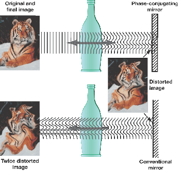
http://encyclopedia.thefreedictionary.com/nonlinear+optics
Optical phase conjugation
Comparison
of a phase conjugate mirror with a conventional mirror. With the phase conjugate
mirror the image is not deformed when passing through an aberrating element twice.
It is possible, using nonlinear optical processes, to exactly reverse the propagation
direction and phase variation of a beam of light. The reversed beam is called a
conjugate beam, and thus the technique is known as optical phase conjugation (also
called time reversal, wavefront reversal and retroreflection).
~This is the negative energy source. The Phase Conjugate wave
coming back at the source wave from the mirror(s). Whether the mirror is a magnet
or not, the nucleus is still involved.~
The most common way of producing optical phase conjugation is to use
a four-wave mixing technique, though it is also possible to use processes such as
stimulated Brillouin scattering. A device producing the phase conjugation effect
is known as a phase conjugate mirror (PCM).
For the four-wave
mixing technique, we can describe four beams (j = 1,2,3,4) with electric fields:......
~Further on in the article....~
.....Note that the constant of proportionality between the signal and
conjugate beams can be greater than 1. This is effectively a mirror with a reflection
coefficient greater than 100%, producing an amplified reflection. The power for
this comes from the two pump beams, which are depleted by the process. ...... ~And amplified by the magnets
yeilding more than was input.~
~This is a good one about Four Wave Mixing. Our stuff is towards
the end but the basic explanations are at the beginning of course.~
http://www.physics.montana.edu/students/thiel/docs/FWMixing.pdf
~The nonlinear medium is of course the magnet. I feel that the
medium being a magnet is benificial although not absolutely necessary. Being a magnet
actually makes it an amplifier because of the free energy being generated/captured
from the vacuum is coming from the lines of flux which are in motion and are Free.
A magnet is a spacetime distortion, constantly collecting free energy from the vacuum,
pouring out it's magnetic flux. Here's another thought... The difference
between the Virtual Vacuum and the Observable is a kind of broken symmetry... a
kind of special Dipole. When spacetime is stressed, a sort of concentrating 'lens'
is formed attracting more and more virtual particles, increasing the stressed area,
and attracting even more particles. This stressed area can (probably) only hold
so much energy and becomes saturated (full if you will). Thus if there is no load
or sink to tap the energy, it becomes a 'static' entity, in waterfall fashion.
The motion of this stressed area (input signal) in the presence of the bi-filar
coil allows the coil to adsorb some of this energy.~
http://encyclopedia.thefreedictionary.com/Time+Reversal+Signal+Processing
Time Reversal
signal processing is a technique for focusing waves. A Time Reversal Mirror (TRM)
is a device that can focus waves using the time reversal method. TRMs are also known
as time reversal mirror arrays, as they are usually arrays of transducers, but they
do not have to be arrays.
~An array of transducers, in this case, can be the atoms in
the Phase Conjugate Material even though an array isn't required. The nucleus
being the actual transducer. It doesn't have to be a magnet..... Barium titanate
is a phase conjugate material in it's own right.~
Bearden, http://www.cheniere.org/techpapers/vanflandern.htm
The ordinary
vector divergence of the curl is zero in a flat spacetime, but it is not necessarily
zero in a curved spacetime. The self-oscillating particles of the medium do provide
sufficient spacetime curvature to allow some of the normal divergence-free Heaviside
component to be diverged anyway, thus furnishing an extra Poynting energy flow input
(diverged) component.....
~Off topic somewhat....~
http://encyclopedia.thefreedictionary.com/magnetic+field
In SI units,
B and H are measured in teslas (T) and amperes per meter (A/m), respectively; or,
in cgs units, in gauss (G) and oersteds (Oe), respectively. Two parallel wires carrying
an electric current in the same sense will generate a magnetic field which will
cause a force of attraction to each other. This fact is used to generate the value
of an ampere of electric current. Note that while like charges repel and unlike ones
attract, the opposite holds for currents: if the current in one of the two
parallel wires is reversed, the two will repel.
~Considering that magnetic flux has a 'direction', N
to S outside the magnet, I think that looking at the flux like it's a current
can help with the understanding of the attraction/repulsion mechanism. Two magnets
can be as two different 'currents', thus when S is put to N the 'current'
is traveling in a 'like sense'. Inward on the S and outward on the N. Just
a thought, speculation.
Well, that's it for now. Simple and complicated at the same
time. Our Paradigm's are our box. We need to be outside the box and I think
we're getting there.
OK everybody, tear it apart. Find the mistakes so the corrections
can be made. I found a few along the way so there's a good chance that I made
more. I can't think of everything by myself and I'm not perfect. I look
forward to seeing what you think.
Have a fresh day everybody. Dale
|
|
Well more coming soon as always.
|
|
4/05/2006 2:42:27 AM
|
10/10/2013 2:42:27 AM
|

|
Edit |
Details |
Delete
|
|
Floyd "Sparky" Sweet - VTA Replication Project
|
NEW FORM OF INDUCTION?! "It's Induction, Jim, but not as we know it" I believe Floyd Sweet's Space Quanta Modulator, or better known as the Vacuum Triode Amplifier, used a form of Induction not well known by many. I show theory and experiments by other researchers that are in excess of COP > 100,000.00 - This Technology is Over Unity. The world is about to change!
|
|
|
Hi Everyone,
Today I am going to explain where my research is leading
me. First of all, if the picture of everything is taken, all the facts, speculations
and outright wrong information, we can see patterns. Patterns that tend to show
mostly the same things but sometimes they can be misleading also.
Floyd Sweet was without a doubt a genius. But his
technology may not have been his. It may have been an adaptation of other technologies
as I will show below.
First I want to start with some quotes from the latest
information we have been given:
|
|
|
Reference:
|
Quote:
|
|
Space-Quanta
Modulator - Clean-Propulsion Power Now! -
The Space-Quanta
Modulated Mark 1 Static Alternator
|
Laboratory experiments
dealing with magnetic fields support the concept that magnetic flux may be modulated
by low level oscillatory means. However there is no lateral movement of flux. Rather,
what happens is that the individual packets of quanta are polarized by the initiating
and sustaining coherent force the field of the primary magnets or in special cases,
electromagnets.
As the low level
oscillatory frequency (modulating frequency) from the oscillators pass through zero
reversing polarity during . The quanta, being polarized, flip in synchronism with
the modulating frequency, presenting a change in flux polarity varying with time
determined by the period of the oscillator frequency. Stationary field and stationary
stator coils are featured in the machine. Except for a possible low level 60 Hz
hum, the alternator is noise-less. There are no bearings or moving parts.
|
|
Space-Quanta
Modulator - Clean-Propulsion Power Now! - The Space Quanta Modulator: How it Works
|
Very low power is
needed to modulate the quanta, which is in a coherent state under the influence
of the residual effects of energy initially consumed in the so-called magnetization
process. This energy is steady state and is actually orientated space quanta, which
is not a property of the magnet, but initiated by the initial magnetizing force.
|
|
Space-Quanta
Modulator - Clean-Propulsion Power Now! and Letter to Mark
|
The number of turns
per coil is determined by Faraday's law as quantized by Neumann. Stranded wire
is used for ease of winding. This wire is specially insulated, and over this insulation
is wound a current feedback winding spirally traversing the total length of the
coil conductor. Also a voltage winding of considerably smaller wire and more turns
is also wound axially, traversing the total length of the coil conductor. The respective
leads are brought out to terminals, and to these terminals is connected the output
of the current and voltage sensing transformers. We now have, when the current and
voltage windings are excited, another set of fields virtually in quadrature with
the fields (alternating) initiated by the load current flowing in the power phase
coils. The current and voltage initiating fields are in such a direction to either
accelerate or decelerate the rate of flow of charges depending on the applied polarity
and voltage amplitude.
|
|
Space-Quanta
Modulator - Clean-Propulsion Power Now! - The Space Quanta Modulator: How it Works
|
The architectural
configuration of the windings and their relationship to the magnets will be best
understood by observing the construction of a prototype. The defining equations
are similar to those of the dynamic Space Flux Coupled alternator. A working prototype
should be ready about Easter.
|
|
Lab Notes - Floyd
Sweet 0005
|
Explanation is unknown
but Sparky believes that "Static Flux Quanta", which are normally in a
disordered state, come into coherence in proximity to a magnet, and feels that the
magnetic field is a result of interaction of the relativistic quantum effects of
the magnetic materials atomic structure in unpaired parallel electron Spin states,
net domain orientation, spin-orbital coup-linings, etc...
|
|
Lab Notes - Floyd
Sweet 0004
|
It seems to be affected
by the quality of the sine wave, negatively by harmonic distortion, such as that
of the Moon Valley oscillator (Circuit on P8 26 - 7)
|
|
Lab Notes - Floyd Sweet 0008
|
Out in space - unintegrated
- Space-Flux Quanta in proximity of Mag they become Integrated :. Field is not a
prop of magnet which has vector quantities (lines of force) which directs quanta
(analogy : water guided by a pipe) 10^100 energy of matrix
|
|
|
It does not take a rocket scientist to see that the
Magnets in the Space Quanta Modulator had a purpose. To see the fact that Floyd
did not alter the Magnetic Field in so far as to "Damage" the field, is
also not hard. Quotes like: "Stationary field and stationary
stator coils are featured in the machine" and "Rather,
what happens is that the individual packets of quanta are polarized by the initiating
and sustaining coherent force the field of the primary magnets or in special cases,
electromagnets." Please remember these are Floyds words.
Lots of other quotes could be taken but I have just used what I believe to be the
best.
Its important to take the whole picture into account.
Floyd is talking about "Quanta" and "Modulating" it as such.
"Quanta" can mean anything at all. It could be the Magnetic Field out
in Space, or it could be the "Quanta" in the Copper Power Coils themselves!
If a Load was to be Powered by "Negative Energy" the Load would need to
be directly Connected to the actual source of this Negative Electricity! Soon you
will see why this is so important to understand!
Why would "Modulating" "Quanta" in the Copper Power Coils be
a likely candidate for the Operation of the Space Quanta Modulator? Lets have a
look at the properties of Copper. Ref:
http://en.wikipedia.org/wiki/Copper
|
|
|
General properties
|
|
Name,
symbol,
number
|
copper, Cu, 29
|
|
Pronunciation
|
/ˈkɒpər/
KOP-ər
|
|
Element category
|
transition
metal
|
|
Group,
period,
block
|
11,
4, d
|
|
Standard atomic weight
|
63.546(3)
|
|
Electron configuration
|
[Ar] 3d10
4s1
2, 8, 18, 1
|
|
History
|
|
Discovery
|
Middle Easterns
(9000
BC)
|
|
Physical properties
|
|
Phase
|
solid
|
|
Density (near
r.t.)
|
8.96 g·cm−3
|
|
Liquid density
at m.p.
|
8.02 g·cm−3
|
|
Melting point
|
1357.77 K, 1084.62
°C, 1984.32 °F
|
|
Boiling point
|
2835 K, 2562 °C, 4643 °F
|
|
Heat of fusion
|
13.26
kJ·mol−1
|
|
Heat of vaporization
|
300.4 kJ·mol−1
|
|
Molar heat capacity
|
24.440 J·mol−1·K−1
|
|
Vapor pressure
|
|
P (Pa)
|
1
|
10
|
100
|
1 k
|
10 k
|
100 k
|
|
at T (K)
|
1509
|
1661
|
1850
|
2089
|
2404
|
2834
|
|
|
Atomic properties
|
|
Oxidation
states
|
+1, +2, +3, +4
(mildly
basic oxide)
|
|
Electronegativity
|
1.90 (Pauling scale)
|
Ionization
energies
(more)
|
1st: 745.5 kJ·mol−1
|
|
2nd: 1957.9 kJ·mol−1
|
|
3rd: 3555 kJ·mol−1
|
|
Atomic radius
|
128 pm
|
|
Covalent
radius
|
132±4 pm
|
|
Van der Waals radius
|
140 pm
|
|
Miscellanea
|
|
Crystal
structure
|
face-centered cubic
|
|
Magnetic ordering
|
diamagnetic[1]
(I believe this bit to be wrong!)
|
|
Electrical resistivity
|
(20 °C) 16.78 nΩ·m
|
|
Thermal conductivity
|
401 W·m−1·K−1
|
|
Thermal expansion
|
(25 °C) 16.5 µm·m−1·K−1
|
|
Speed of
sound (thin rod)
|
(r.t.)
(annealed)
3810 m·s−1
|
|
Young's
modulus
|
110–128 GPa
|
|
Shear modulus
|
48 GPa
|
|
Bulk modulus
|
140 GPa
|
|
Poisson
ratio
|
0.34
|
|
Mohs hardness
|
3.0
|
|
Vickers hardness
|
369 MPa
|
|
Brinell hardness
|
874 MPa
|
|
CAS registry number
|
7440-50-8
|
|
|
Because of Coppers Electron Configuration, it is a
Paramagnetic Material. I
reference Wikipedia:
"Paramagnetism is a form of magnetism whereby
certain materials are attracted by an externally applied magnetic field. In contrast
with this behaviour, diamagnetic materials are repelled by magnetic fields. Paramagnetic
materials include most chemical elements and some compounds; they have a relative
magnetic permeability greater or equal to unity (i.e., a positive magnetic susceptibility)
and hence are attracted to magnetic fields. The magnetic moment induced by the applied
field is linear in the field strength and rather weak. It typically requires a sensitive
analytical balance to detect the effect and modern measurements on paramagnetic
materials are often conducted with a SQUID magnetometer.
Paramagnetic materials have a small, positive susceptibility to magnetic fields.
These materials are slightly attracted by a magnetic field and the material does
not retain the magnetic properties when the external field is removed. Paramagnetic
properties are due to the presence of some unpaired electrons, and from the realignment
of the electron paths caused by the external magnetic field. Paramagnetic materials
include magnesium, molybdenum, lithium, and tantalum.
Unlike ferromagnets, paramagnets do not retain any magnetization in the absence
of an externally applied magnetic field because thermal motion randomizes the spin
orientations. Some paramagnetic materials retain spin disorder at absolute zero,
meaning they are paramagnetic in the ground state. Thus the total magnetization
drops to zero when the applied field is removed. Even in the presence of the field
there is only a small induced magnetization because only a small fraction of the
spins will be oriented by the field. This fraction is proportional to the field
strength and this explains the linear dependency. The attraction experienced by
ferromagnetic materials is non-linear and much stronger, so that it is easily observed,
for instance, by the attraction between a refrigerator magnet and the iron of the
refrigerator itself."
This means that Copper and other materials can exhibit
a Paramagnetic Effect in the proximity to "the field
of the primary magnets or in special cases, electromagnets."
So see where I am going with this? Now, you will say: "Hang on a minute here,
this means nothing". Well, actually that could not be further from the truth.
The quote: "a voltage winding of considerably
smaller wire and more turns is also wound axially, traversing the total length of
the coil conductor." is an important
point of interest. I will show here why.
First some history on this idea or topic:

"In the Ural Mountains in 1992, a Russian geologist
accidentally discovered what would later be known as Russian nano spirals. The discovery
of the Russian nano spirals, or more correctly miniscule spiral-shaped objects,
was made while investigating mineral deposits. The artefacts were made from copper,
tungsten, and molybdenum. The objects ranged in size from the largest that was about
1 1/18 inches to the smallest which was only 1/10,000th of an inch. These curious
findings bore an eerie resemblance to the control elements used in recently developed
“nano-machines”all of the pieces were found at depths between 10 and 40 feet, embedded
in gravel and detritus deposits. These deposits corresponded to the lower region
of the Mikulinsk Horizon of the upper Pleistocene Era, suggesting that the objects
themselves may be around 100,000 years old. There is no possible way such objects
could be embedded so deeply without having ancient origins.
All of the objects appear to be manufactured as no type of natural process known
could explain their creation. How humans 100,000 years ago would have been able
to be technologically advanced to such a degree as to be able to create them is
unknown. Is this mysterious discovery evidence that humans may have been more technologically
advanced than previously believed or are the objects evidence of extraterrestrial
contact or presence?"
Referenced from:
http://oddx.com/2011/11/russian-nano-spirals/
And now a little more recent:
An Article Published; "Science et Vie" nr.700
March 1976 ( pages 42-45 ), by Renaud de la Taille, and also French Patent # 2,385,255, French Patent # 2,680,613 and Czechoslovakia Patent # 284,333.
The article published in "Science et Vie"
nr.700 March 1976 ( pages 42-45 ) is entitled: "A POWER PLANT AT HOME".
Click Here for the English Translation.
(Please note: This document is in early stages of
the Translation and may change.)

Here you can see the similarities to Floyd Sweets
first
Generation 1 Space Quanta Modulator!
Un-cannily, the quote: "a voltage winding
of considerably smaller wire and more turns is also wound axially, traversing the
total length of the coil conductor."
is exactly one of the next experiments of Richard VIALLE as you will see in the
videos.
Is there anywhere else we can see more evidence that
this technology is real and exists? - YES, I have left the best till last. Richard
VIALLE's work has been measured to be in excess of
COP > 100,000.00! Its being worked on by many people:
Don't forget to turn on the Captions:

Also Jean Louis Naudin has done some excellent
replications:
http://jnaudin.free.fr/rvproject/index.htm
Use Google Translate to read:
http://translate.google.com/
The Energy Out is Negative Energy. It is from Atomic
Interactions of Paramagnetic Modulated Quanta. So you can see here, if I am right
and this turns out to be the source of Floyd Sweets Energy Output, then it was never
about the Magnets! "Rather, what happens is that the
individual packets of quanta are polarized by the initiating and sustaining coherent
force the field of the primary magnets or in special cases, electromagnets."
Floyd has told us all along what he has done. He has just left out the part of how
to. We have to figure this stuff out for our selves. Thanks to Michel Meyer, Richard
VIALLE and Jean Louis Naudin we have now at least some information and experiments
that can be done to start to understand how this New Form of Induction works.
|
|
|
4/05/2013 2:48:19 AM
|
10/10/2013 2:48:19 AM
|

|
Edit |
Details |
Delete
|
|
Floyd "Sparky" Sweet - VTA Replication Project
|
A Video Update today. I am sure we are on the right track with this theory. Too much information fits into place with this current information and we also have very good evidence to support this idea. This is not in the realms of MAGIC and Mysticism, its scientifically proven with devices out there that can very easily show the effects I have explained.
|
|
Hi Everyone. Just a video update today.
|
|
4/11/2013 1:47:41 PM
|
4/11/2013 1:47:41 PM
|
|
Edit |
Details |
Delete
|
|
Floyd "Sparky" Sweet - VTA Replication Project
|
Simulations show good results and common sense says this should work. Data is fitting together nicely and a lot of things are now explained.
|
|
|
HI Everyone,
Frame Dragging, The "Lense-Thirring Effect"
or The "Protational Field" is seen in the Pictures below.
Click Here to learn more. It makes me laugh, three names for the same thing,
science is very scientific isn't it. Astronomy uses this technique when searching
for Planets and other objects in the universe. Clearly shown to be possible in the
VTA or SQM below. All the information is fitting together now. I have had so much
trouble over the years to try to fit all the data together. I have got I believe
90 % of it in my mind done. Experiments soon will be done to see if this works.
I think I might take Mr Rosenthal's advise and put it on a trailer when I am ready
to go and run the experiment in the outback. To explain the pictures there
are two magnets top and bottom in attraction mode like Floyd said. We have two Bifilar
coils in the centre the same as in the Schematics I have shown. I will re insert
below.
First we show magnets in attraction mode and
no coils.
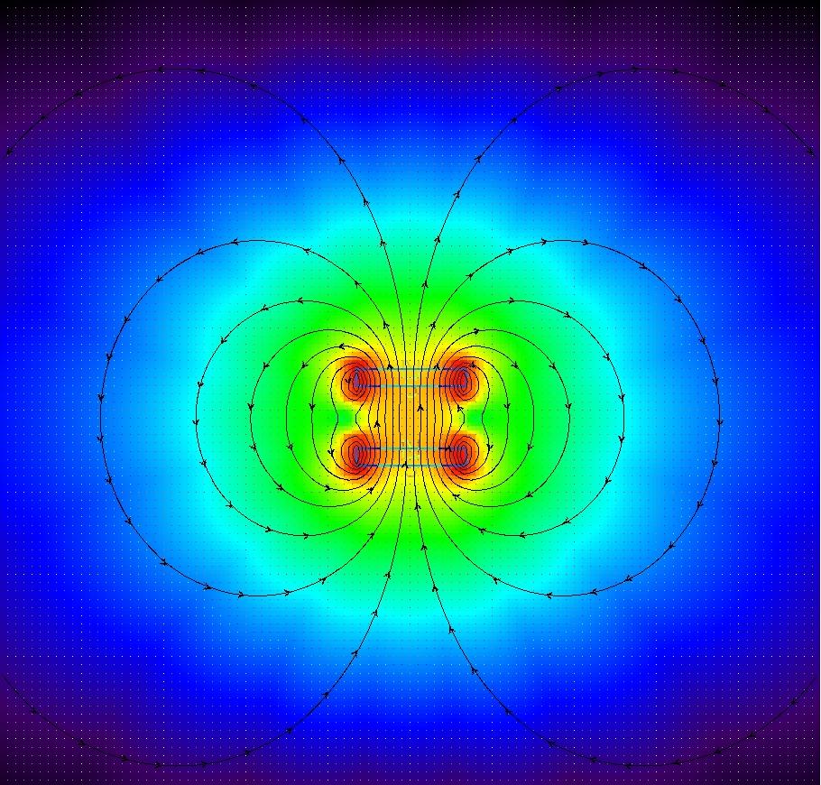
Now we introduce the coils and start the SQM:
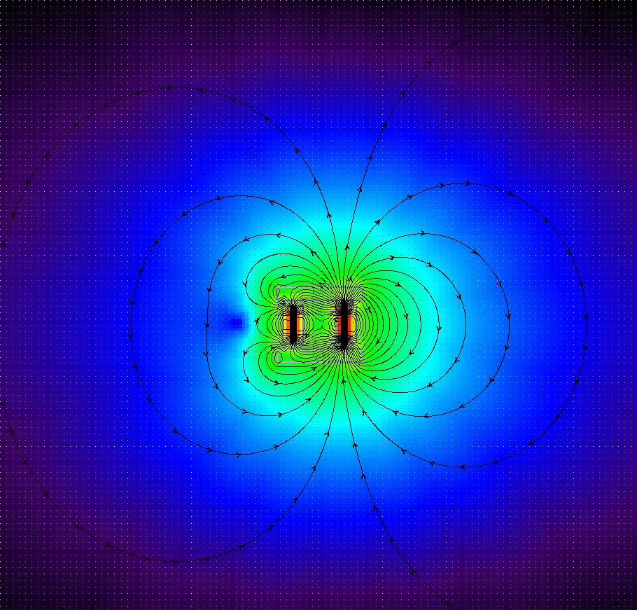
This is the second half of the sine wave oscillation:
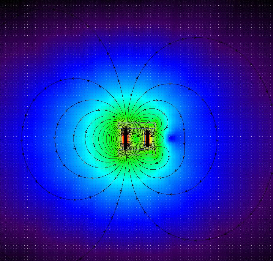
Here is a movie, average quality of the fields in
action: Click Here
There is a lot of good theory here and common-sense
says this should work as described in the Nothing is Something paper. Again conditioning
the magnets is starting the SQM and to Start the SQM the output coils must be in
the SQM and connected to a load. The coils are what keeps the magnets flux in motion
as shown above. The Daniel McFarland Cook Electromagnetic Battery has the same method
of operation and should have produced the same results as Floyd had. That was more
than a hundred years ago. 1871. Ref:
http://my.voyager.net/~jrrandall/CookCoil.htm
Well more coming soon as always.
|
|
5/03/2008 2:58:17 AM
|
13/11/2013 6:57:56 AM
|

|
Edit |
Details |
Delete
|
|
Floyd "Sparky" Sweet - VTA Replication Project
|
Today I am going to show a simple experiment that disproves the "Conditioning" process that was described by Tom Bearden. Floyd gave Tom Bearden information that is easily disproved in one very simple experiment. VTA Magnet Conditioning, as was described, is proven FALSE through Experiment!
|
|
|
Hi Everyone,
Today I am showing a very simple experiment that proves the Magnet "Conditioning"
as was described to be FALSE!
I deeply respect Tom Bearden - this man has dedicated
his life to humanity and done the best he can to get information out there to people!
If Floyd Sweet was a bit more open on how he did what he did we would not have to
do so much work to see what he really did end up doing. So please don't take this
information as a targeted attack on Tom Bearden because it is not!
Permanent Magnet
"Conditioning" in the sense where the Field of the Magnet was waving back
and forth, was a Red Heiring given
to those that were close to Floyd. For years we have all been told that this was
the "Achilles Heel" of the VTA of the late Floyd Sweet.
|
|
VTA Magnet Conditioning, as was
described, is proven FALSE through Experiment!
Ref: Tom Bearden: "Here is the magnet sitting
on the table absolutely still no body moving a thing, but the field, the magnetic
field of the magnet is waving back and forth. And , So, you can take a shim stock
or if you're out of shim stock, a single edge razor blade, and put on this permanent
magnet, and with a little trouble you can get it to stand up in that field and you
can get it to wave back and forth, and just turn it loose, and it will sit there
on a properly conditioned Sweet magnet it will sit there and wave just like, now
it's doing work all the time against the air, I want to point this out, this thing
is doing work, so it's getting energy somewhere."
|
|
|
|
We may have a clue to what Floyd did in the wise
words of Waler Rosenthal.
Ref: Energy From The Vacuum - Part 15 - SEEKING OVERUNITY
Chapters from free energy history with the late Walter Rosenthal: "When I showed
the magnet to the guy, he took a little device, and he moved it across the magnet
face, and he could see and I could see that, well, I knew this was a Magnet that
Floyd had worked with it just was one that was not currently functioning, the polarity
around the periphery of the Magnet was reversed, Now the magnet normally all South
on one side and all North on the other side. But every magnet that Floyd ever got
his hands on after he had been playing with for a while, it was reversed around
the periphery. The significance of that I don't know, really."
|
|
This is not
how the VTA could have worked!
|
|
|
5/03/2012 3:11:05 AM
|
19/10/2013 5:54:16 AM
|

|
Edit |
Details |
Delete
|
|
Floyd "Sparky" Sweet - VTA Replication Project
|
Flux Gate Magnetometers and how they work. We have a video demonstration today with Power draw and we see that the Output of the device has no effect (or very little effect) on the Input. In other words there is no relationship from the Input to the Output. The Flux Gate Magnetometer or Induction Compass or Saturable-Core Compass is said to be what Lester Hendershot based his device on also.
|
|
|
Hi Everyone,
Today we are experimenting with FGM's (Flux Gate Magnetometer)
and learning more about the Magnetic Field and how moving the field is easy when
the right understanding is obtained. Its actually a very simple device in appearance
and easy when the right understanding is obtained. The first two I built were not
a good as the third.
How the Flux Gate Magnetometer works:
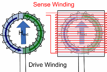
It is important to think of the Ring Core as two separate
halves, Flux Modulates here.
Ref:
Imperial College London Please visit for a very good explanation of how the
FGM works.
I have used this basic device for the experiment.
I removed the coils taped in black and wound one big coil on the outside of both
formers.
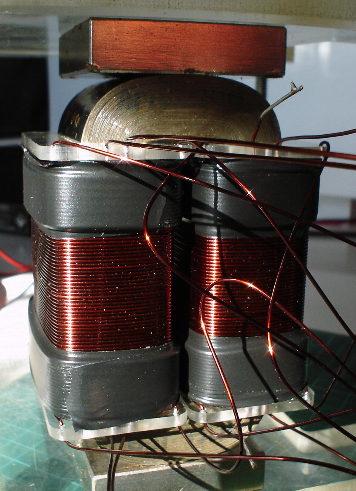
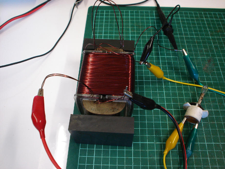
There are some real considerations to be made here,
the Core is the biggest problem. I did not get the explanation out very well in
the video, but, the BH Curve is very important and Saturation of the core by the
Magnets is a real problem. Funnily enough the BH Curve is related to the Aharonov
Bohm Effect Tom Bearden talks about. Now we have data that says Floyd used Air Cored
Coils and we know Air cant be saturated. Could this be why Floyd used Air Cored
Coils?
Typical BH Curve:

As the Permanent Magnets move onto the Core, the Core
BH Curve changes and the Domains in the Core get harder to move due to the External
Magnetisation.
Remember John Bedini said: "Here are the only tools Sweet had. Small oven,
old TV set, Amplifier, the rest Walt R built.". (Funny that an Amplifier is needed to run the above FGM project)
A Quote from Tom Bearden: "The
device serves as a gate or switching device for polarized vacuum energy.". Tom has always said, the Device acts like a
Triode, and it "Gates" Energy. Walter Rosenthal
said: "The VTA
"likes" to always see a minimum load
of 25 watts."
Could this be because it does take some "Feed Back" energy to keep the
VTA Driven. It is also important to note again another quote from Rosenthal: "The VTA can be started by momentary
connection of a 9-volt battery to the drive coils when the machine is operated in
the self-powered mode. The operation is stopped by momentary interruption of power
to the power coils." Walter Rosenthal
did also supply us with this schematic:
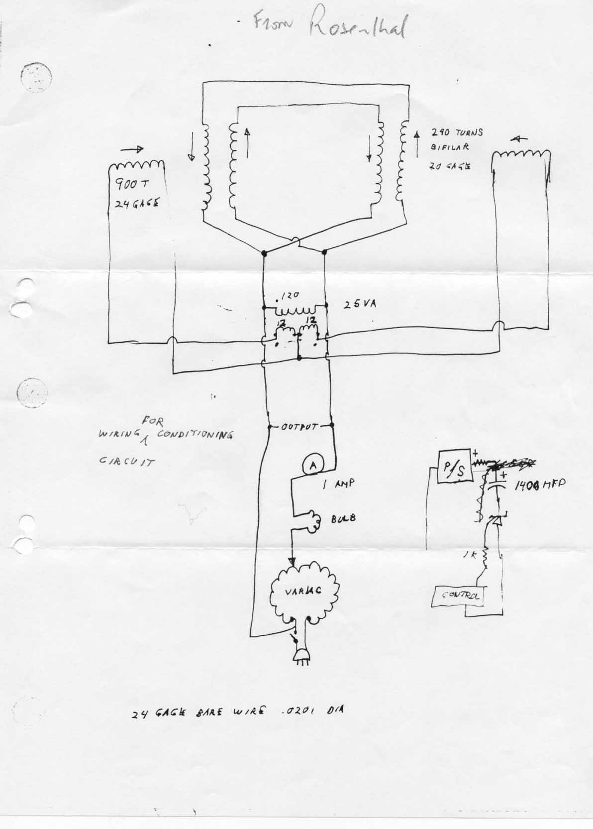
Notice the feed back in the below picture referred
to in the last Update 30-03-10 in Sparky -- 1987 document.

and notice the similarity to the FGM
Could it be that the VTA (or the Space Quanta Modulator)
is simply an advanced version of a Flux Gate Magnetometer? Logic certainly seems
to point to this possibility!
Click Here to download an animation of the Flux gate Magnetometer
I hope everyone had a happy and safe Easter. Our thoughts
are with the Californians in the 7.2 Earth Quake that hit today.
|
|
|
5/04/2010 3:30:06 AM
|
10/10/2013 3:34:06 AM
|

|
Edit |
Details |
Delete
|
|
Floyd "Sparky" Sweet - VTA Replication Project
|
An addition to yesterdays Update with part 2 of the series. We further explain how the VTA of the late Floyd Sparky Sweet worked. Its just amazing, maybe divine intervention? It certainly feels like it. Pay if forward when you get yours working. Please look after your fellow brothers and sisters. After all we are all supposed to be working together, not against each other!
|
"Sweet
was also a transformer designer and expert, and he remarked that
he had also observed specialized self-oscillation in certain transformers."
Ref:
Energy From
The Vacuum by Tom Bearden
"On rare occasions,
Sweet saw this effect, called self-oscillation, occur in electric
transformers"
Ref:
http://merlib.org/node/5282
|
|
5/11/2013 5:24:25 PM
|
5/11/2013 5:24:25 PM
|

|
Edit |
Details |
Delete
|
|
Floyd "Sparky" Sweet - VTA Replication Project
|
This update is old but important documents from E T Whittaker the 1903 document is a bit hard to find and read easily from the internet. The 1904 document is easy but I wanted them both together for reading purposes.
|
|
SQM Replication Project Update 07-03-07.
I was looking around on the net and
just out of curiosity decided to look for the E T Whittaker papers that Mr Bearden
speaks about from 1903 and 1904.
I found the 1904 paper easy but the
1903 is hard to find. I had these documents in archive but realising how important
these documents are and reading then several times I decided to post them in an
update.
E.T.Whittaker 1903.pdf
E.T.Whittaker 1904.pdf
Please download and distribute them
freely.
|
|
7/03/2007 4:24:11 AM
|
14/10/2013 1:29:25 PM
|

|
Edit |
Details |
Delete
|
|
Floyd "Sparky" Sweet - VTA Replication Project
|
Happy New Year Everyone. Most of you may already know the principals behind the Bifilar Coil. If not then this is definitely worth a read.
|
|
|
HI Everyone,
I want to share this Information as it is very important
to understand the principals behind this coil. There is a difference between Self
Inductance and Inductance. Self Inductance is a coils ability to induce a current
in itself in the opposite direction of the current applied to the coil. Thus energy
is wasted in the energising of the coil as energy is used in overcoming the Self
Inductance. This coil (Nikola Tesla's Patent No. 512,340) is a very important coil
because of its characteristics, firstly to reduce the Self Inductance (Nikola Tesla
said to zero) but I would say that this depends on the coils configuration. E.g.
Compound coil vs. Flat coil. It is important to note this coil is not a non inductive
coil. It is a Bifilar Inductive non Self Inductive coil. Here are the following
types of Bifilar coils:
Four types of bifilar-wound coils:
-
parallel-wound, series connected
-
parallel-wound, parallel connected
-
counter-wound caduceus coil (series)
-
counter-wound caduceus coil (parallel)
Ref:
http://en.wikipedia.org/wiki/Bifilar_coil
Mobius Coils are different again and are not what
I am currently interested in. Here is a good link for more information.
http://www.rexresearch.com/davis/davis.htm These coils are sometimes used
in resistive Inductors as the above link says. We don't want to turn energy to heat
and waste it we want to use it for Motive Force. To do Work. These coils have also
been around for a very long time.
UNITED STATES PATENT OFFICE.
NIKOLA TESLA, OF NEW YORK, N.Y.
COIL FOR ELECTRO-MAGNETS
SPECIFICATION forming part of Letters
Patent No. 512,340, dated January 9, 1894.
Application filed July 7, 1893. Serial
No. 479,804. (No model.)
To all whom it may concern:
Be it known that I, NIKOLA TESLA,
a citizen of the United States, residing at New York, in the county and State of
New York, have invented certain new and useful Improvements in Coils for Electro-Magnets
and other Apparatus, of which the following is a specification, reference being
had to the drawings accompanying and forming a part of the same.
In electric apparatus or systems in
which alternating currents are employed the self-induction of the coils or conductors
may, and in fact, in many cases does operate disadvantagely by giving rise to false
currents which often reduce what is known as the commercial efficiency of the apparatus
composing the system or operate detrimentally in other respects. The effects of
self-induction, above referred to, are known to be neutralized by proportioning
to a proper degree the capacity of the circuit with relation to the self-induction
and frequency of the currents. This has been accomplished heretofore by the use
of condensers constructed and applied as separate instruments.
My present invention has for its object
to avoid the employment of condensers which are expensive, cumbersome and difficult
to maintain in perfect condition, and to so construct the coils themselves as to
accomplish the same ultimate object.
I would here state that by the term
coils I desire to include generally helices, solenoids, or, in fact, any conductor
the different parts of which by the requirements of its application or use are brought
into such relations with each other as to materially increase the self-induction.
I have found that in every coil there
exists a certain relation between its self-induction and capacity that permits a
current of given frequency and potential to pass through it with no other opposition
than that of ohmic resistance, or, in other words, as though it possessed no self-induction.
This is due to the mutual relations existing between the special character of the
current and the self-induction and capacity of the coil, the latter quantity being
just capable of neutralizing the self-induction for that frequency. It is well-known
that the higher the frequency or potential difference of the current the smaller
the capacity required to counteract the self-induction; hence, in any coil, however
small the capacity, it may be sufficient for the purpose stated if the proper conditions
in other respects be secured. In the ordinary coils the difference of potential
between adjacent turns or spires is very small, so that while they are in a sense
condensers, they possess but very small capacity and the relations between the two
quantities, self-induction and capacity, are not such as under any ordinary conditions
satisfy the requirements herein contemplated, because the capacity relatively to
the self-induction is very small.
In order to attain my object and to
properly increase the capacity of any given coil, I wind it in such way as to secure
a greater difference of potential between its adjacent turns or convolutions, and
since the energy stored in the coil considering - the latter as a condenser, is
proportionate to the square of the potential difference between its adjacent convolutions,
it is evident that I may in this way secure by a proper disposition of these convolutions
a greatly increased capacity for a given increase in potential difference between
the turns.
I have illustrated diagrammatically
in the accompanying drawings the general nature of the plan which I adopt for carrying
out this invention.
Figure 1 is a diagram of a coil wound
in the ordinary manner.
Figure 2 is a diagram of a winding designed to secure the objects of my invention.
Let A,
Figure 1, designate any given coil the spires or convolutions of which
are wound upon and insulated from each other. Let it be assumed that the terminals
of this coil show a potential difference of one hundred volts, and that there are
one thousand convolutions; then considering any two contiguous points on adjacent
convolutions let it be assumed that there will exist between them a potential difference
of one-tenth of a volt.
If now, as shown in Figure 2, a conductor
B be wound parallel with the conductor A and insulated from it, and
the end of A be connected with the starting point of B, the aggregate
length of the two conductors being such that the assumed number of convolutions
or turns is the same, viz., one thousand, then the potential difference between
any two points in A and B will be fifty volts, and as the capacity
effect is proportionate to the square of this difference,
the energy stored in the coil as a whole will now be two hundred and fifty thousand
as great.
Following out this principle, I may wind any given coil either in whole or in part,
not only in the specific manner herein illustrated, but in a great variety of ways,
well-known in the art, so as to secure between adjacent convolutions such potential
difference as will give the proper capacity to neutralize the self-induction for
any given current that may be employed. Capacity secured in this particular way
possesses an additional advantage in that it is evenly distributed, a consideration
of the greatest importance in many cases, and the results, both as to efficiency
and economy, are the more readily and easily obtained as the size of the coils,
the potential difference, or frequency of the currents are increased.
Coils composed of independent strands
or conductors wound side by side and connected in series are not in themselves new,
and I do not regard a more detailed description of the same as necessary. But heretofore,
so far as I am aware, the objects in view have been essentially different from mine,
and the results which I obtain even if an incident to such forms of winding have
not been appreciated or taken advantage of.
In carrying out my invention it is
to be observed that certain facts are well understood by those skilled in the art,
viz: the relations of capacity, self-induction, and the frequency and potential
difference of the current. What capacity, therefore, in any given case it is desirable
to obtain and what special winding will secure it, are readily determinable from
the other factors which are known.
What I claim as my invention is:
- A coil for electric apparatus
the adjacent convolutions of which form parts of the circuit between which there
exists a potential difference sufficient to secure in the coil a capacity capable
of neutralizing its self-induction, as herein before described.
- A coil composed of contiguous
or adjacent insulated conductors electrically connected in series and having a potential
difference of such value as to give to the coil as a whole, a capacity sufficient
to neutralize its self-induction, as set forth.
NIKOLA TESLA.
Witnesses:
- Robert. F. Gaylord
-
Parker W. Page
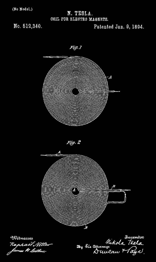
Thanks to:
http://www.magnetricity.com for
the very well presented information on these coils.
Some Extremely interesting information in this link:
Click Here This illustration really shows
the massive benefits behind this coil.
Well more coming soon as always.
|
|
|
8/01/2008 4:28:04 AM
|
10/10/2013 4:28:04 AM
|

|
Edit |
Details |
Delete
|
|
Floyd "Sparky" Sweet - VTA Replication Project
|
Amazing NEW Video Evidence of the VTA. Floyd "Sparky" Sweet - Forgotten Genius.
|
|
|
Excellent New Evidence!!!!
This is amazing, I have not seen such good evidence
of the VTA Layout before. This video just reconfirms the current track we are on.
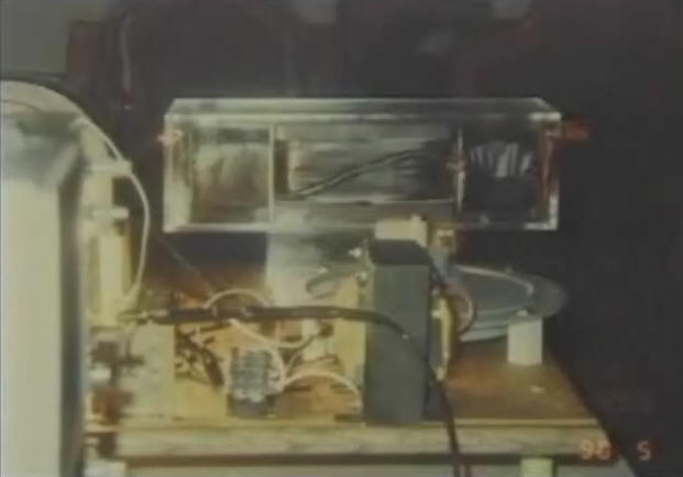

|
|
|
8/09/2009 4:35:29 AM
|
10/10/2013 4:35:29 AM
|

|
Edit |
Details |
Delete
|
|
Floyd "Sparky" Sweet - VTA Replication Project
|
Well the ideas I had were not successful and this is very important in the SQM's progress. This either means the SQM had a secret configuration before the successful reported conditioning of the magnets or the magnets were in oscillation before the reported time. This contradicts all information in the SQM's history which is big in itself. I mean really, Where is the energy coming from?
|
|
SQM Replication Project Update 8-10-05.
It is not from the magnets as such or the original SQM would have had a configuration that was fairly conventional and a small output would be achieved (Say 6 watts like the original SQM). Simply information is not adding up on this project and some answers are needed. I think a few misleading truths have been told in the history of the SQM which is a shame. AND REALLY WHAT IS THE MOTIONAL E-FIELD???? It is obviously very important or it wouldn't be in the "Nothing is Something" Paper by Mr Sweet.
This is an email
I have sent to Mr Bearden in an attempt to further understand the SQM. I have had
small Oscillations in the magnets but for short times and no output of any relevance
is achievable, this was partly documented in the forth video update. Questions grow
and the SQM project looks more difficult everyday. By now everyone must know how
important the MOTIONAL E-FIELD is and that it cant be shielded and that it is so
very important and the capacitors electro static field is dispersed evenly along
a capacitor plate. Well if not read the paper "nothing is something" by
Mr Sweet. I am sure it has been modified and that there are only parts in their
that are important. How would one GENERATE a motional E-Field. What is needed and
how can it be done with 10 V and 1/3 of a mill Amp. One could say frustration has
set in.
Dear Mr Tom Bearden,
I have several
questions for you. I have been working on the replication of the Sweet SQM for more
than 12 months now. Several things don’t make sense on this project and Mr Sweet
must have had the same problems. The Motional E-Field is Key to understanding this
device and only this alone can explain the energy conversion in the SQM. Can you
explain the Motional E-Field in extreme detail as this is a non conventional Field
Effect that is very important to all devices weather it is conventional or not.
The second thing
is, does the energy collection come from the Eather or is it transformed from the
Eather that surrounds us. If it is transformed, in what process could it be transformed
to energy that we use. Mr Nikola Tesla transformed the Eather but he was not a mare
peasant he was special and had a natural understanding of the problems he faced.
Is the Motional E-Field shuttling energy into the collection coil at a determined
frequency and the collection coils geometry is the transformation medium.
Does the Excitation
coils geometry and composite expose the driving force. I have been working on the
magnets structure for more than 12 months now and they have no negative effects
even if in oscillation which I have had for a small time. Absolutely no NEGATIVE
effects have been observed with any oscillation on Barium Ferrite magnets.
You said in your
last letter the lattice structure had to be right but the lattice can only be in
one motion at any one time. If Mr Sweet had changed the SQM in mid stream like you
mentioned in your email and at that point he had successfully had conditioned his
magnets, then where did the 6 Watts come from. What was the SQM's construction before
the conditioning was achieved
I have only achieved
at any one time 1 Volt out of any device at any time and this is with the magnets
oscillating which will dissipate in a short period. No energy collection Is gathered
with all configurations tried.
I have come to
only one conclusion, this must be a non conventional construction that was privy
to Mr Sweet and the coils MOTIONAL E-Field was extremely important in the understanding
of this device. Only the MOTIONAL E-Field will make this device work and only in
one way. Absolutely no Over Unity output is achievable unless the motional E-Field
is understood and time is awasting.
You can understand
the importance of self-sustaining ourselves in the energy field. It does not even
come into the fact of National security, Hurricane Katrina proved that with out
a doubt. Millions of people DEAD in future disasters will not be a problem, even
with terrorism on our door step, if this can be averted by self sustainable family’s
that can pack and move with the comforts of home included by a short move to a near
by community of safety from natural disasters.
Money means nothing
to anyone if people are dying to get it. Some can and some can’t achieve an understanding
here and I do think it is possible to give the world the greatest gift of all right
here. Imagine the Independence of people if they have energy at their finger tips.
We are now mature enough to stand and accept responsibility for our future and terrorism
can’t stop that fact.
Kind Regards
Chris
Sykes
Maybe information in this email will
revel new information on the true SQM's nature and a replication will be more achievable
and the time frame will be lowered as a result!!!!
|
|
8/10/2005 4:44:00 AM
|
10/10/2013 4:44:00 AM
|

|
Edit |
Details |
Delete
|
|
Floyd "Sparky" Sweet - VTA Replication Project
|
Did the VTA have a Core Material? We show very good evidence that supports that the VTA did have a core. We still cant be 100% sure so we stay partial on this topic.
|
| I want to say, I really feel for John Bedini.
I was under the impression that the last Part 30 of Energy from the Vacuum
was a little bit of a directed negative response toward the Floyd Sweet
VTA Replication Project. I have always had the utmost respect for John Bedini,
Tom Bearden and Walt Rosenthal. These guys in my opinion are heros and I
have always looked up to their wise words. Unfortunately if information
is incorrect then I have to point this out as John Bedini has also done.
John, I feel your hurt, its obvious on your face in Part 30.
Some VERY basic Experiments to disprove and prove some
information. Facts are Facts and experimental proof cant be disputed.
|
|
8/11/2013 11:26:14 AM
|
8/11/2013 3:20:44 PM
|

|
Edit |
Details |
Delete
|
|
Project HHO - Stan Meyer Hydrogen Fuel Cell
|
I just want to share what I have done with the HHO Technology. My production was only average and not anything amazing.
|
|
Hydrogen Fuel
Cell Technology
HI Everyone,
I want to share
this as it has been a side project for many years. Some of my close
friends know my progress on this technology. All credit to Stan
Meyer with this technology and sharing t with us. I was part of
the early Joe Cell groups and had a bit of success in this group
but was disheartened about a few things. The circuit I am using
is a modification of the Dave Lawton Circuit which has been changed
a bit since these pictures were taken. The transformer is a 240/14v@3amps
out with the 14v@3amps connected between (in series) with the positive
input into the cell. The diode is to stop b-emf coming back into
the circuit and put it back into the Cell to increase HHO output.
I am rectifying the 240v output and dumping it back into the cell
also. It seems to help a bit but maybe only 2-3 percent if even
that.
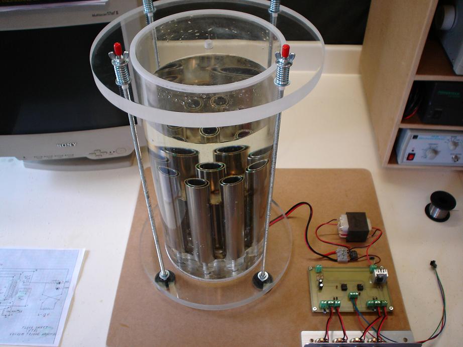
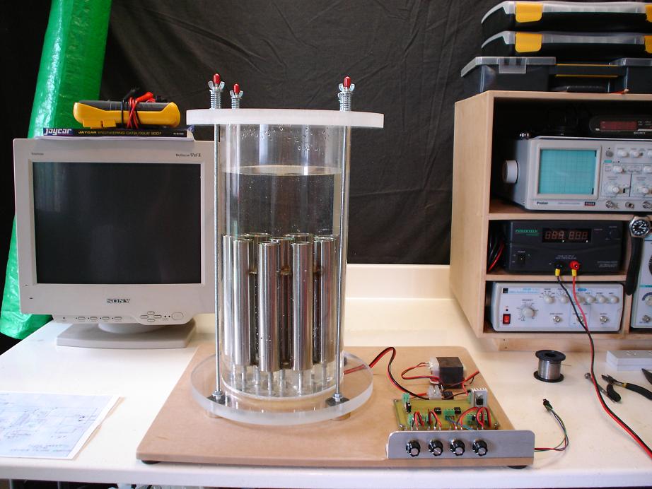
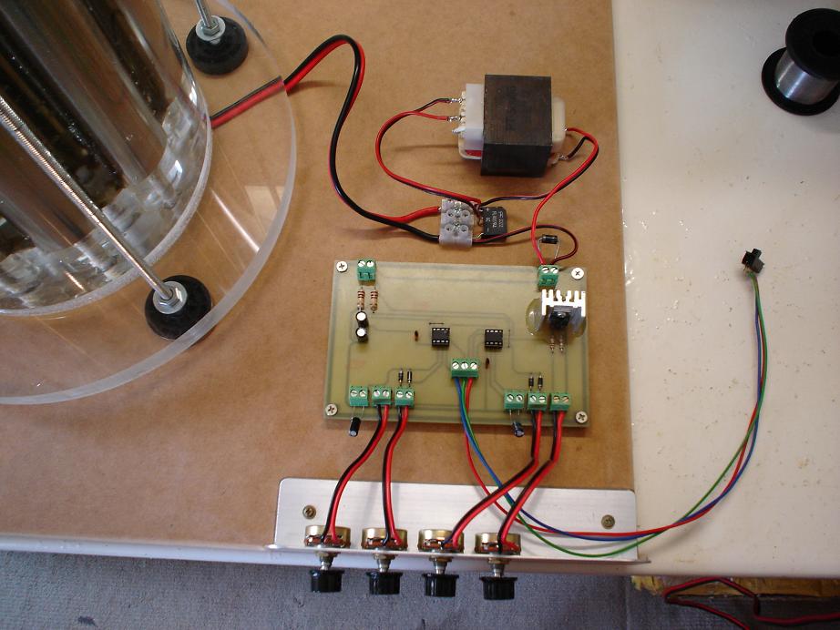
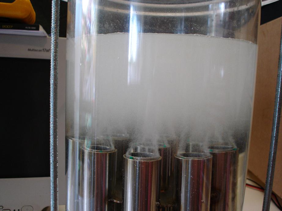

In place of
the Tip29 NPN Transistor I am currently using a SSS10N604 - 107
from Fairchild as I am getting a faster pulse time for the power
input I am using. Also less heat and Power wastage.
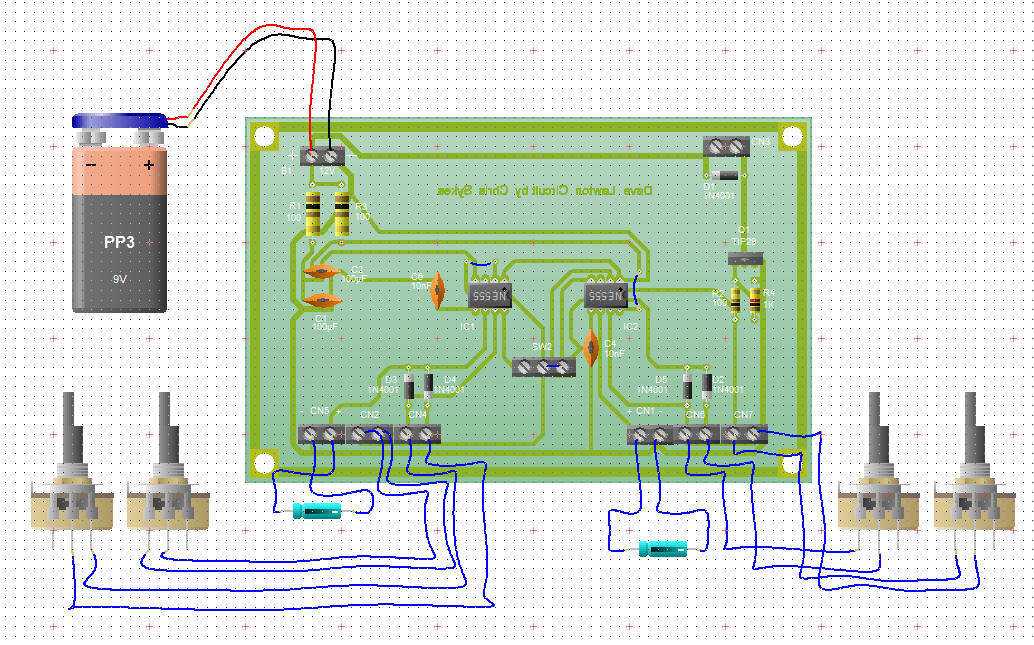
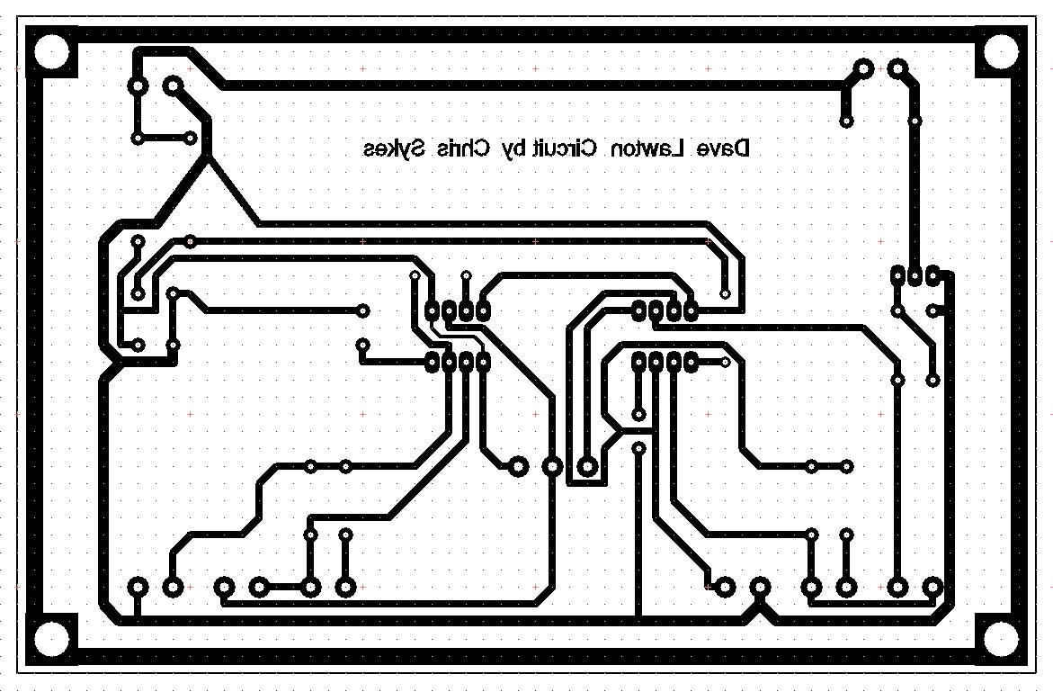
I can put straight
DC into this cell and it draws 21 Ampers. Heats up the cell and
I get brown dirty Water. No real benefit to the cell or the efficiency
of the cell. With pulsed DC and the Coil in the transformer I can
limit the input current and get some good efficiencies as you can
see in the Pictures. I have not measured the output yet and currently
do not have any plans to. I am of the opinion that HHO is a good
technology but has a big dependency that Magnetic devices do not
have. A dependency on fuel - Water.
Dave, Thanks
for sharing your expertise with us ;0). Download my version of the
Dave Lawton Circuit.
Click Here
Use Circuit
Wizard to open this file. 30 Day trial can be
downloaded
here
Well more coming
soon as always.
|
|
|
|
10/02/2007 1:43:43 PM
|
11/10/2013 11:53:26 AM
|

|
Edit |
Details |
Delete
|
|
Floyd "Sparky" Sweet - VTA Replication Project
|
I have made a few mistakes with Naming conventions and this update s to point this mistake out. I must apologise for my mistake.
|
|
SQM Replication Project Update 10-07-06.
Hi Everyone, it has been pointed out
that some of my naming conventions are not quite correct in the last few updates.
For example the Positron being the Electrons anti Particle and not the Proton. In
beta plus decay, a proton is converted to a neutron via the weak nuclear force and
a beta plus particle (a positron) and a neutrino are emitted. So if this is taken
into account then maybe the Electrons in a wire are changed to a different state
due to this very fact. Positrons are annihilated instantly as far as we know but
on annihilation they must leave some affect on its surrounding environment being
the magnetic or Electric field.
Thanks to Dave and Dale for pointing
this mistake out.
Well more coming soon as always.
|
|
10/07/2006 4:48:24 AM
|
10/10/2013 4:48:24 AM
|

|
Edit |
Details |
Delete
|
|
Floyd "Sparky" Sweet - VTA Replication Project
|
Perhaps the most important Project Update in the history of the VTA Replication Project! We believe we have cracked the riddle. Enough information is now known to replicate the VTA, the real Vacuum Triode Amplifier, or the Space Quanta Modulator of Floyd "Sparky" Sweet! I have been looking for the Jensen Document for a long time and have found it!
|
Floyd Sweet and his study of Energy Machines
We know that Floyd did study Energy Machines. He wrote about and also
describes one in particular, the "Jensen Amplifying Transformer". This is
an astounding Fact! Unfortunately I am unable to date the document that
Floyd wrote about the device.
Floyd Sweet and the "Jensen Amplifying Transformer"
We believe we the
Jensen Unidirectional
Transformer may be the same device as Floyd Sweet studied and described
in his paper: "Magnetic
Resonance by Floyd A. Sweet. PH. D" but instead refers to as the "Jensen
Amplifying Transformer".
The document refers to the Jensen Transformer in various ways at least
three times. Floyd Sweet was a very bright guy, why would he pay so much
attention to such a device? Also another question begs to be answered: If
the VTA was an off shoot of the great Gabriel Kron's "Negative Resistor"
or some may like to refer to it as the "Network Analyser" then why would
Floyd even need to study in such detail the Jensen Unidirectional Transformer?
It seems to me, we have the answer right in front of our eyes once again.
I believe there is sufficient evidence to say that the VTA works on the
same principals as the Jensen Unidirectional Transformer and so do many
other devices through history.
We quote from Floyd:
"Let’s assume the Jensen amplifying transformer is in a resonating
condition. Its output is connected to a transmission line which is X number
of miles long. Without any customer load at all, power will be required
to change the line. This will present capacitive reactance, Xc = 1/2 fc.
The power factor cos angle Phi will be leading, though negligible on short
systems. The effect must be reckoned with on multiple grid long systems
operating above 60 KV. What we have is a capacitor and the effects are evident
as line impedance. Another parameter is varying power factor due to changing
inductive loads. Taken together this forms a complex impedance load continually
varying and this is what the "Jensen" machine will "see" when connected
to power distributing network grids."
At this point in time, Floyd may have not been fully aware of the actual
operation of the Jensen Amplifying Transformer, although Floyd did clearly
state: "The concept has merit but if pursued further R & D should be
in the 60 Hz power frequency area." The Jensen Unidirectional Transformer
did use a 60Hz model and also implies that High Frequency Models were also
possible. The document "The Jensen Unidirectional Transformer" was released
in 1994, however the publish date, or the date of the experiments on the
device could have been much earlier on. Floyd Sweet dies in 1995 the year
after the document was put into the public domain. Floyd started to get
results as early as 1985, mostly 1986 which we have documents to support
this date so a 10 year gap is quite possible for such a device to become
known to a selected few before the device was published in the public domain.
We quote from the Jensen Paper:
"An alternate explanation for the current gain in the UDT is to consider
each secondary winding as acting as the primary winding for the other secondary
winding when an output current is drawn because the two secondary windings
generate geometrically opposing fields."
The above statement is perhaps one of the most interesting statement
anyone has ever written about the energy gains in Energy Machines. If we
re-visit the schematics and re-draw with what we have learned we can see
some amazing clarity's!
Taking into account the written description of the VTA:
"Consider for a moment the
construction of the triode which includes the bifilar coils located within
the fields of the two conditioned magnets.
When the current in one
half of the conductors in the coils (i.e., one of the bifilar elements in
each coil) of the device is moving up, both the current and the magnetic
field follow the right-hand rule.
The resultant motional E-field would be vertical
to both and inwardly directed.
At the same time the current in the other
half of the conductors in the coils is moving down and both the current
and magnetic field follow the right-hand rule.
The resulting motional E-field is again vertical
to both and inwardly directed.
Thus, the resultant field intensity is double
the intensity attributable to either one of the set of coil conductors taken
singularly."
Problem!
We can not have two "motional E-field's vertical to both
and inwardly directed" at the same time!!! It just can not occur in the
known VTA geometry!!! To make provision for this issue we now get something
like this: (See below Videos for more information)
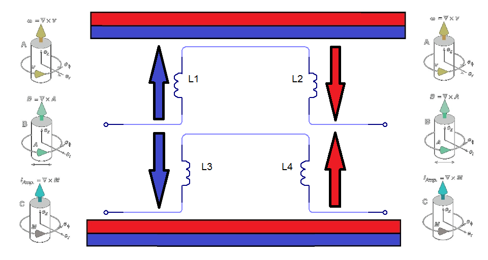
Where both the current and the magnetic field follow
the right-hand rule. (Indicated by Arrow Direction)
Again I would like to quote from the Jensen Paper:
"An alternate explanation for the current gain in the UDT is to consider
each secondary winding as acting as the primary winding for the other secondary
winding when an output current is drawn because the two secondary windings
generate geometrically opposing fields."
Yes: "geometrically opposing fields." We know that in this configuration,
that this, is sometimes referred to as a Scalar Field. It also supports
the idea that the Scalar Potential "Drive Coils" on the ends of the VTA
were in fact, there to keep the VTA running, a feed forward and back arrangement,
to supply current to the FB1 and FB2 Coils. We note how the VTA is started
in the original schematic.
I think there is enough evidence to say the Power coils did in fact have
a core material. I think there is also enough evidence to say that it is
possible the core was not just a single core, but in fact may have been
split into two separate cores in each single Power Coil, each having two
separate windings to complete the singular Power Coil. For anyone that has
not seen how this can work, please study either, or preferably both, the
Ward Force Device by Steve Ward (Generator that short Circuits Lenz's Field
on its self with the use of a small gap) and the Kromrey Converter (A Generator
that appears to show more power generated in the power coils to extrude
the Permanent Magnets Flux in the core, that generated the EMF in the first
place) (Thus making the Core invisible to the Magnetic Field). This implies
that the Magnetic forces through the low reluctance of the Magnetic Core
are sufficient to generate an EMF to reduce the reluctance of the Core material,
close to, or to zero over coming the initial Magnetic Forces.
The Magnetic Field
A Charged Particle moving in space or in a medium creates a Magnetic
Field. If we wanted to make the charged particle move faster, we need to
find a way to reduce its Magnetic Field. The Magnetic Field acts as a Break
in some situations. Thus, we commonly see heating of Coils in Transformers,
Generators and so on, that's proportional to the power output drawn.
Take two separate sources of Magnetic Fields, opposing, North to North
squeezed together, if one was to apply the superposition rules, this would
mean that it cancels the Magnetic Field. This is not entirely true unless
the source of each Magnetic Field occupies the same physical space at the
same time and with the same magnitude. In saying this, the Magnetic Field
is greatly reduced the tighter the Magnetic Fields are squeezed together.
I have done a very simple experiment that can easily show this is true.
E.G:
Use a CRT TV screen, turn on the TV and set the screen
to blue or some solid colour, tape one Magnet on the screen, in the middle,
with one pole facing out of the screen. Now push another Magnet into the
Magnet on the screen with the Magnetic Fields opposing, North to North,
or South to South, watch the field decrease in size on the screen. This
experiment is very easy and provable every day of the week.
So with: "geometrically opposing fields" we can see
why this is important. It is a way to reduce Lenz's Law, It creates a self
feed back mechanism in the power coils that have an EMF generated in them,
and reduced Lenz's Law means that the output can go above unity. The very
requirement here is that Charges must be flowing for this process to occur.
Gennady Markov and his Bi-Directional Current Transformer.
I wish to also make reference to Gennady Markov and his
Bi-Directional Current Transformer. This Transformer also works on the same
principals. It has been awarded a Russian Patent. This is a very interesting
device, it also incorporates a gap in the Core material and also Coils facing
toward each other, E.G.: North to North. Please see the related documents
below for more information. This concept is the key to these devices and
a new science.
Update on Experiment:
I have confirmed that the current ideas and theories do work as I
have said. Here is a very simple experiment that can show some very
astounding results.
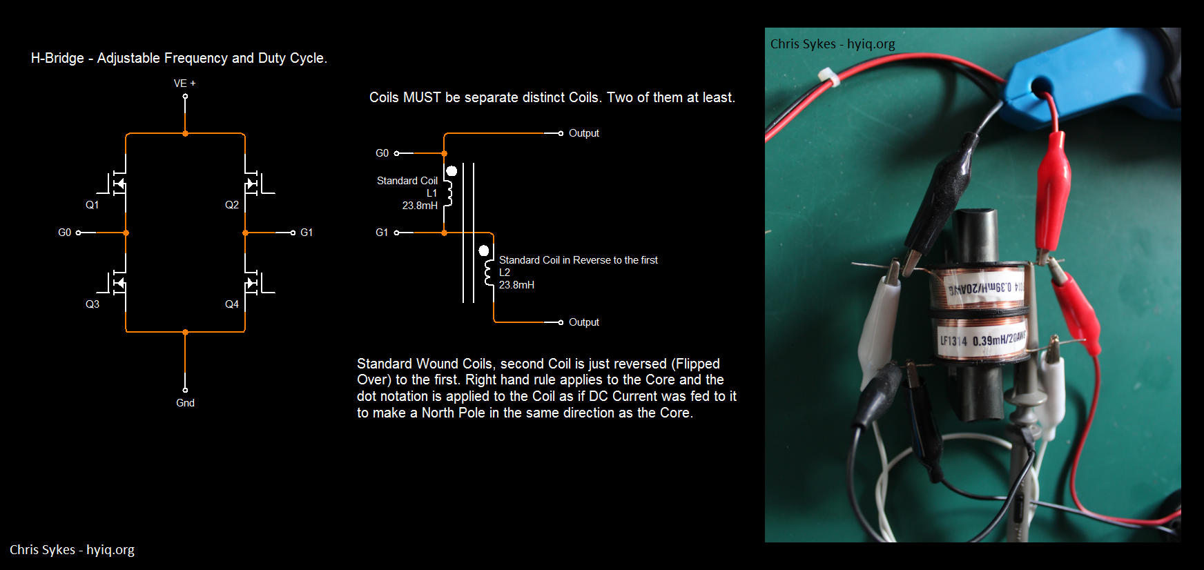
How to do it!
1: Coils must be 2 separate
distinct coils as is shown in the Schematic.
2: Coils must be Wired and orientated to Buck - Cancel the Magnetic
Field but Electric Field does Add. Just like Floyd Sweet said!
3: I suggest low Duty Cycle, 8% or so, at low frequency (20
- 100 Hz) just to test initially.
4: Start with low voltage on the input, slowly turn it up.
Once you're there you will see what I mean.
You will get:
1: Two Output pulses for one Input pulse.
2: Output is NOT affected by Input, Lenz's Law doesn't apply
from input to output! (May need a little fine tuning to get the best result)
3: A small amount of Energy is needed to keep this effect going,
Power input is very small.
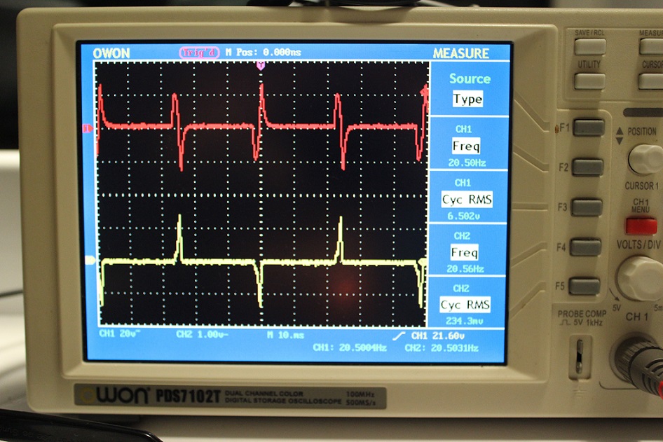
Where:
Red Trace is the Output Voltage.
Yellow Trace is the input Current.
EDIT: This is an old video I made some time back. I have
decided that it would be valuable to others:
Note: This Globe is a 12V, 300ma (3.6 Watt) Globe. I
am getting very good illumination for 1 Watt (5v * 200ma).
The visual evidence surely speaks for itself here.
Related Document's:
Magnetic Resonance by Floyd A. Sweet. PH. D:
Click Here
Gennady Markov - Bi-Directional Current Transformer:
Click Here
Gennady Markov - Bi-Directional Current Transformer: Patent CA2224708
Click Here
Related Videos:
|
|
11/02/2014 11:54:11 AM
|
3/11/2014 8:54:30 AM
|
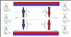
|
Edit |
Details |
Delete
|
|
Floyd "Sparky" Sweet - VTA Replication Project
|
More good news, I have got resonance on top of the big conditioning coil now after purchasing a 15 cell car battery. More power to the amp has increased the field slightly but it is still not as strong as Mr Sweet had it in the video. I am going to put this down to magnet depth and better production of the magnets now with higher field strengths.
|
|
SQM Replication Project Update 11-04-05.
I am still close to the first attempt of conditioning the magnets but a few small things I am not yet happy with:
1/ Time to discharge the capacitor is still causing the SCR/Thyristor to latch.
I am still thinking my direction here may not be right. I have briefly tested the SCR oscillator circuit with no success. This is what I need. Capacitor to discharge and to turn off the SCR with back EMF. This could be a single discharge of the capacitor but is more likely to be a discharge in oscillations other wise this does not explain the bulb in the video oscillating in brightness.
2/ Increase if possible the resonance affect at the top of the large coil, the blade is waving or oscillating but is is fairly lightly oscillating.
There is a bit of a delicate balance in this setup for the conditioning. Tuning and adjusting after time will give the desired results here and I hope we get the results with the magnets after this is all done. I am thinking more and more that it will. I found these quite good articles about magnets also there is some mentions of instabilities of the magnets and that's what I think we are going after. Click Here.
Something I am finding interesting is the amount of pages on the net that have been taken down when you search for "Spin wave instability magnon distribution for parallel pumping". Interesting ;o) Lucky I have a few books about this phenomena.
There looks to be a trigger or a triac
as was said in the video. This is interesting because I have not noticed before
the wire from the AC side of the Diode Bridge to the triac or trigger.
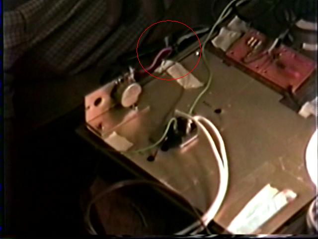
The amount of wire pair to the conditioning
coil is at the moment undecided. I can make out at least three wires if not four.
How many pairs is my question? I am guessing four pairs.
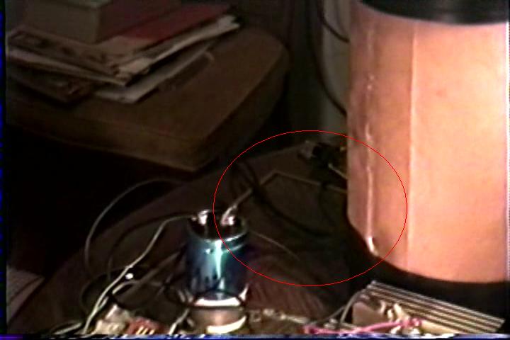
|
|
11/04/2005 4:51:03 AM
|
10/10/2013 4:51:03 AM
|

|
Edit |
Details |
Delete
|
|
Floyd "Sparky" Sweet - VTA Replication Project
|
Just a small update today. This is just to let you know I have got the voltage where I want it for the conditioning and explains the Wave I am now using which is so important to be able to achieve the goal of replicating the SQM.
|
|
|
SQM Replication Project Update 11-06-07.
Hi Everyone, some news. I have got the voltage I want
so I can proceed with more experimentation. I am currently getting max voltage of
675 Volts on the capacitors before discharging. I am going back through Mr Tom Bearden's
Email and information that he sent me more than two years ago now. I hope this makes
more sense as it was a bit beyond me back then. You know I think Mr Bearden is a
great man, he is on the ball. I am on track now and it is just a matter of time
before I am able to share the process. Most of the process is already on my site
as far as I believe. It is just a matter of time before I get the procedure down.
Also I just want to point out that the Whittaker Papers
1903 and 1904, and the Video "Radionics - Action at a Distance" is the
key to where I am now. This information is a very important to get the understanding
of the wave I have shown and why this wave is important to get the conditioning
achieved.
I have in my last update shown how to catch Radiant
Energy like Mr Bedini has talked about for years. This is a step to the road ahead.
It is also, if done right, a path to COP>1 if one is to spend time to refine
the process. In this circuit Energy recovery is part of the process.
Well more coming soon as always.
|
|
|
11/06/2007 4:55:38 AM
|
10/10/2013 4:55:38 AM
|

|
Edit |
Details |
Delete
|
|
The MEG Replication Project
|
First of all we need to be clear on how the MEG Works. Here we look at the principals and run simulations on how we think the MEG could work.
|
| |
The
MEG Replication Project by hyiq.org
Please Note: The MEG is a Patented
Device. hyiq.org has been granted permission for this Replication by The
MEG's Inventors.
|
Very early construction
and some eager pre testing to see if I can see anything amazing.
Being this is just an early setup I will not be posting to much
information.
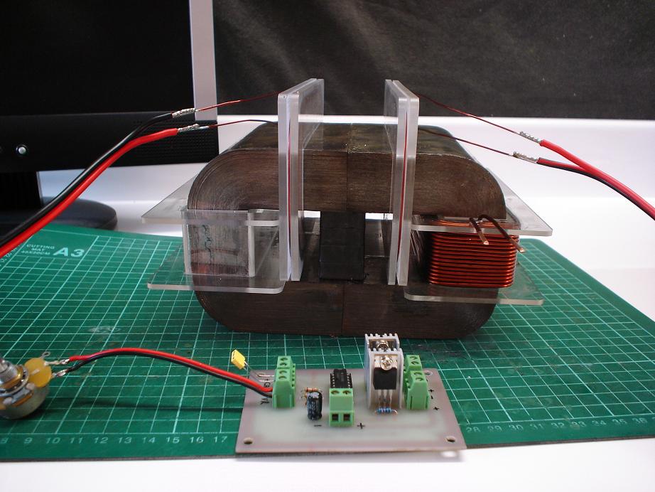
You can see
my cores are very large and rather heavy. Working on cores this
big with out popper Winding machines is a bit difficult. You can
see below how big the cores actually are.
MEG Replication:
Within the magnetic world, the last
measurement of a magnet is generally considered the measurement
of which the direction of magnetism travels parallel through.
|
Magnet Type |
Height |
Length |
Width |
| Ferrite
SrFe03 |
40mm |
25mm |
10mm |
I have to be
a little tricky here to make this work. I need to glue all ten Magnets
together to create one Magnet with the right dimensions to fit inside
the Window Area of the MEG's Core. This has to be a nice tight fit.
The Magnetisation is through the 10mm Face, so the North Pole moves
through the Magnet on the 25mm Face parallel with the 10mm Face
to the South Pole to the other 25mm Face. I will need 4 Magnets
high, to make the 40mm and 2 sets of these 3 Magnets long, giving
me 120mm long, with all north poles in one direction and all south
poles in the other direction. If I get a custom Magnet made I will
be looking at minimum purchase restrictions and this is very expensive.
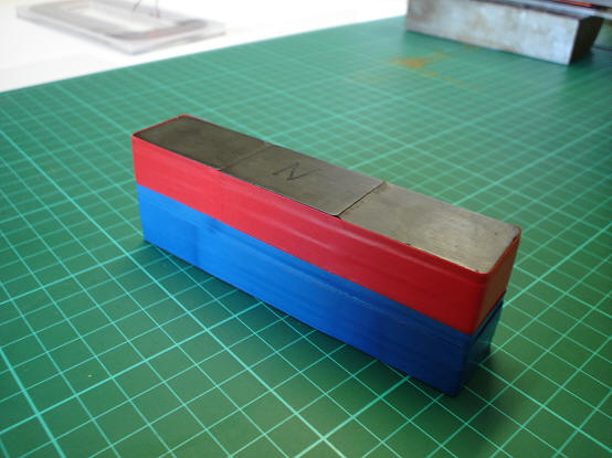
So here you
can see all North Poles of the individual Magnets are facing up
and South Poles are facing down. I have glued 3 sets of 4 magnets
in each set together.
All North Poles
must face in the same direction, this makes pushing the Magnets
together a little difficult as they want to push away from each
other. I used G-Clamps to hold the Magnets in place with an Alloy
Right angle Plate to make sure they are straight and in line when
gluing them.
The Core -
Metglas® Alloy 2605SA1:
| |
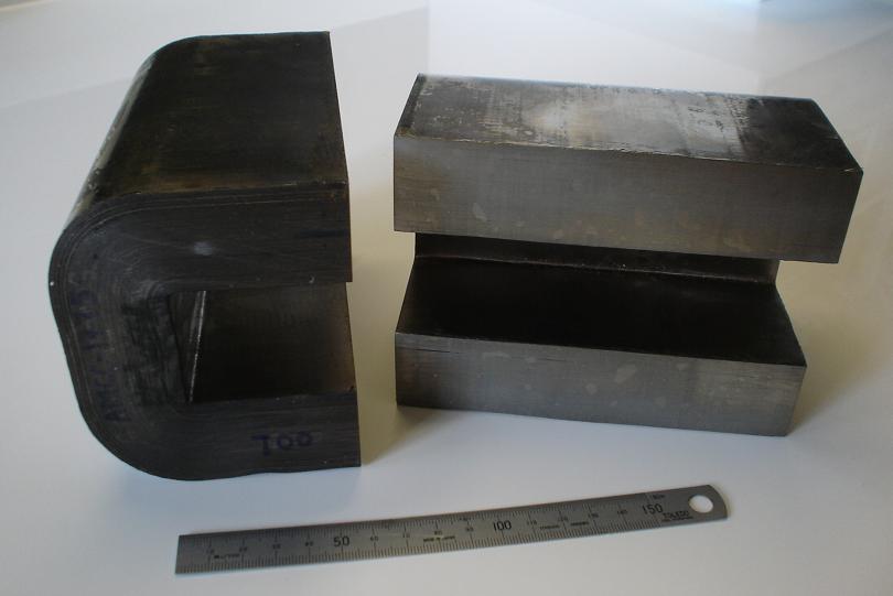
|
|
| |
|
CORE # |
AMCC-1775 |
a
(mm) |
33.0±1.0 |
b
(mm) |
40.5±0.5 |
c
(mm) |
106.30±1.25 |
d
(mm) |
142.00±1.5 |
e*
(mm) |
106.5±2.5 |
f*
(mm) |
172.6+4.0 |
Lm*
(cm) |
39.72 |
Ac*
(cm2) |
39.36 |
Core
Wt.±2%
(gm) |
11466.0 |
Window
Area
(cm2)
|
43.05 |
|
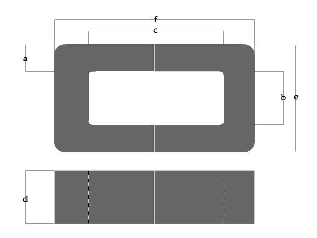 |
|
|
|
I got my cores from
http://www.uaml.net/.
The Contact there is Vikas. He is very helpful. Please mention Chris
from hyiq.org and Vikas will help you out.
|
| The MEG Driver Circuit:
Initially I will be using a variant
of the MEG Circuit from Jean-Louis Naudin.
My replication of Jean-Louis Naudin's
Circuit:
Click Here or on the Picture to download the
Circuit Wizard Circuit File.
Download Circuit Wizard 30 Day Trial here.
Click Here
for the TL494CN PWM Chip Datasheet.
Get your TL494CN's from Mouser Electronics.
The J.L. Naudin
circuit, above, is a 50% Duty Cycle, so the circuit has two channels,
one channel is on 50% of the time then off the other 50%, the other
Channel is 180 degrees out of phase, when channel one is on, channel
2 is off and vice versa.
Most likely
I will be using another circuit to Drive the Actuator coils. This
Circuit will be a basic Fett Switching circuit and more information
will be posted soon about this.
I am also looking
at a 25% duty cycle driver circuit. I am building the circuits modular
for a few reasons. The main reason is that it makes it easier to
change one small part of the circuit if I need to.
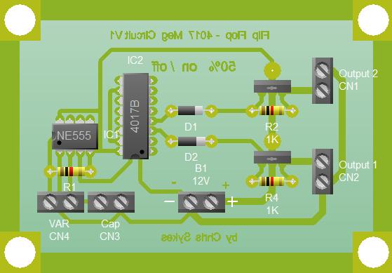
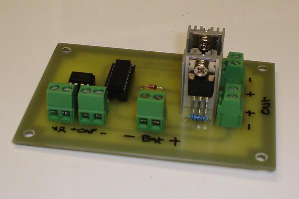
Click Here or on the Picture to download the
Circuit Wizard Circuit File.
Above, in a
25% duty cycle circuit, again we have two channels, the Circuit
is off 25% of the cycle, then channel one moves to an on state 25%
of the cycle, then again the circuit goes into an off state 25%
of the cycle, then channel two moves to an on state 25% of the cycle.
Because 4 x 25% = 100% this is one full cycle. We can see here the
circuit is actually off 50% of the full cycle.
Ref for
Duty Cycle:
http://en.wikipedia.org/wiki/Duty_cycle
|
| |
|
|
|
11/08/2009 5:38:00 PM
|
10/10/2013 5:42:05 PM
|

|
Edit |
Details |
Delete
|
|
Floyd "Sparky" Sweet - VTA Replication Project
|
Facts are Facts and my last Update may not be correct. Floyd "Sparky" Sweet was a bright guy, he clearly shows in his documents that he knew about NMR Induction. Spin Wave technology is currently the terminology. Floyd did not have the right RF Equipment to experiment with this technology. I simply don't think Floyd went down this track of exploration and Floyd had something simpler.
|
| Hi Everyone,
My last Update I was quite confident that I have
finally found an amazing technology that was the answer to all our
questions.
I believe I was wrong about Floyd Sweet using this as
a means of operation of the VTA. I can clearly show that Floyd did know
about this NMR Induction technology but I believe he did not have the
right equipment to make this work correctly. Richard Vialle has
shown excellent ideas and concepts that are proven in the lab. I have
done some experiments and can confirm that this technology works. My
work was not Over Unity however. Please don't dismiss this technology as
being amazing because it is still a very important concept to know
about.
Wave Length
Please Note: For this type of thing to be experimented
on properly, one must take into account some things that have not really
surfaced anywhere. Wave Length of the EM Field Absorbed in the Copper
Coil at the Centre of the Spirally Traversing Coil!
Take the total Length of the Coil, this is the Copper
Wire that is traversed by the Spirally Traversing Coil, The Length of
this wire or coil needs to be One Half, or if you Earth one End of this
Coil, One Quarter the Input Frequency Wave Length.
So for 1 Meter, the Wave Length is 300MHz / 2. This
means that the Richard Vialle U Device should have an input
Frequency of 150MHz input to the Spirally Traversing Coil, or if one was
to Earth one end of the U Device, then you could use a Quarter Wave
Length whish is 75MHz.
Please Note: This is entirely dependant on the
Medium. E.G: In Coax Cable, the Speed of Light is only 66% of the
Speed of Light in a Vacuum, thus Wave Length is 66% Slower, Normal Enamelled Copper Wire is 96% of the Speed of Light
so be careful with exact Calculations.
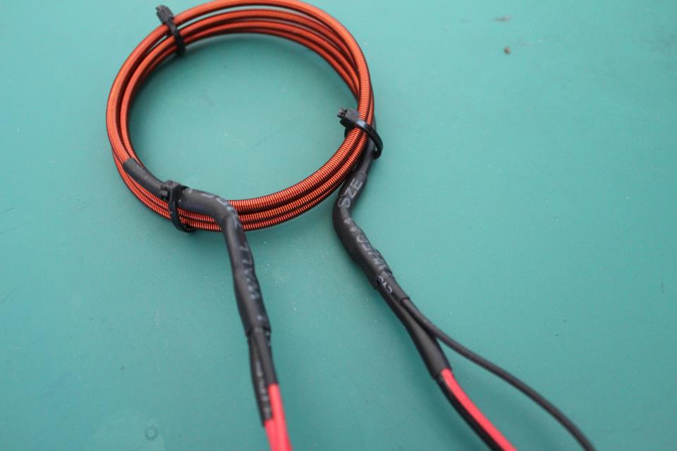
My next Version of the Coil:
My Richard Vialle Replication:
I have for a few years now been pulling my hair out to
find an avenue that may open up that will lead us to more answers to the
VTA. The Vacuum Triode Amplifier was and still is the best option for
clean energy future. I firmly believe this.
|
|
New Look Website!
|
|
For the last year or two I have been in the process of
rebuilding the hyiq.org Website. My early efforts were no good as I just
didn't have the time to put into it. Lately I have put more efforts in
and had a little more time and we have now a brand new Website that is
much easier to navigate and use. Part of the reason I have not been able
to do many Updates lately is because I have spent so much time
re-building the Website.
Login to the community and find all the excellent new features that
we have on offer. You can share Your RnD Project in the RnD Hive, post updates
and show off your work. This is a ranked feature. Enjoy the Live
Community
Chat. Bring Ideas together and chat about results. Share your best links
on our Quick Links System that is also a rated feature.
All we offer is still FREE To you the Public. Please
remember we do run Google Adds to pay for some of the work we do though
so don't forget we very much appreciate your support. |
| |
|
11/10/2013 2:13:49 PM
|
16/10/2013 5:50:54 AM
|

|
Edit |
Details |
Delete
|
|
Floyd "Sparky" Sweet - VTA Replication Project
|
When two systems using AC Currents meet, there is a phasing the needs to be matched so that one does not try to "Drive" the other.
|
|
|
Nikola Tesla arrived in New York on June 6, 1884 moving
from his home country of Croatia, born in 1856
in Smiljan Lika. Nikola Tesla found himself working for the Edison Company of America
soon after arriving. The Edison Company sold DC power to customers, they had many
problems not yet solved. DC Current had a limited life span due to the problems
that came with transmitting DC Current.
One problem the Edison Company had was scaling up
the power plants. Edison could not make a big enough Generator to service all of
his customers so he tried to couple two together. The biggest problem, was when
one Dynamo (back then a Generator was called a dynamo) is high and the other dynamo
was low, the High Dynamo would try to drive the Low Dynamo, thus, the Low Dynamo
would turn into a DC Motor and the High Dynamo would drive the DC Motor. In other
words, if the Phasing of the Dynamos were 180 degrees out of phase then would drive
each other and not be dynamos for supplying power any more. This defeated the hole
purpose of coupling two Dynamos. Coupling two Dynamos together promised to be a
difficult task for Edison.
The Great Nikola Tesla had the opportunity to solve
a big problem that Edison had with trying to couple his big DC Generators. He was
promised $50,000 if he could solve the problem.
Nikola Tesla:
Thomas Edison:
Nikola Tesla solved the problem, it was a simple phasing
problem and all Nikola Tesla had to do was couple the Dynamos together at 0 or at
90 degrees out of phase and not the previous 180 degrees..
Nikola Tesla never received the Money from Edison.
Here we can see a VERY important lesson in Phasing
and what Phasing can do in electrical Circuits. If we let the mind run wild for
a minute we can see some very important implications especially in light of the
recent information surfaced in conjunction with older data and combining similar
technologies we have researched. Our overall picture is expanding and our task at
hand is becoming clearer. Could we be looking at the Motional E-Field if we have
the right Geometry? It certainly looks this way. See Update 08-09-08
for a detailed view on what I mean.font>
Ref: The Man Who Invented the Twentieth Century: Nikola
Tesla, forgotten genius of electricity - by Robert Lomas
|
|
|
11/12/2008 5:02:07 AM
|
10/10/2013 5:02:07 AM
|

|
Edit |
Details |
Delete
|
|
Floyd "Sparky" Sweet - VTA Replication Project
|
The electric Car is, or at least was here. We let it slip away. Some putting up a fight but with no success.
|
|
|
I just saw a documentary this last weekend. Who Killed The Electric Car.
This is am amazing Documentary.
The coincidence is here:
A couple of weeks before his death, Sweet said that
the automotive industry was testing his power unit for use in cars, and that they
had a unit running for 5,000 hours. He said he was dealing with people at General
Motors, but no one has been able to confirm Sweet's claims.
Ref:
A New Physics for a New Energy Source - by Jeanne Manning
In the next picture, we see the EV1 made by GM. The
first all electric modern car. Some famous people had an EV1: Mel Gibson, Tom Hanks
and many other people.
After the leases were up, GM Repossessed the EV1's
and this is what GM did to them.
Some people put up a fight, unfortunately they were
not successful. There is not one EV1 on the road anymore, the last one was removed
from the road in 2005. Electric Cars are not new, we had Electric cars 100 years
ago.
The world’s
first advanced electric car, a 108-year-old vehicle that led to the first hybrid
car that were both developed by Ferdinand Porsche at the turn of the century. Does
this statement sound like a step backwards?
Google
Old Electric Cars
|
|
|
12/07/2008 5:04:09 AM
|
10/10/2013 5:04:09 AM
|

|
Edit |
Details |
Delete
|
|
Floyd "Sparky" Sweet - VTA Replication Project
|
The last 8 days I have changed a few things to try to get as close to the video as possible. Much of my work is guess work and frustration is common with failure. I have had no success with the resonant coil at the bottom of the Conditioning coil.
|
|
13-03-05 Update on experiments.
The magnetic field strength is just not enough to bring the magnets into resonance while the magnets are on top of the Conditioning coil. I started work on the 60 Hz oscillations in the Conditioning coil again and at certain power levels the circuit stops and the transistors fuse. In After fusing several tens of transistors I sat back and thought about the approach I was taking. May be instead of trying to trigger the Conditioning coil via an Audio Oscillator, it would be better to use the Coil and SCR in an oscillating circuit of their own (SCR Oscillator). This circuit would also solve the problem of the Resonant coils field strength not being sufficient to bring the magnets into resonance at the top of the Conditioning coil because the starting voltage and frequency of the Conditioning coil would be the same as the Resonant coil, exactly like the video. For example the input Voltage of say 40 Volts to the Conditioning coil would give this circuit a frequency of around the 8.5 Hz of the resonating Magnet.
Sitting back now this approach seems so simple. The field strength of the Resonant coil is still in question while the magnets are inside the Conditioning coil. Will the field strength be sufficient to open the molecular structure of atoms inside the domains themselves.
Progress has been made. I got some Alloy tube this week to replace the PVC holder for the magnets. They measure 100mm x 150mm x 50mm and fit exactly to the magnets. I will put some pictures up tomorrow.
With the information I have learned after these experiments I expect to have a full video demonstration of the first attempt at conditioning the magnets in two weeks time. This is as long as everything goes well and I don't blowup anymore hardware.
I have received a lot of very good feed back. Suggestions like the Alloy tube that may have eddy current effects, to Coil structure and Circuit information. Thanks to everyone that is so extremely interested in this project.
Here is the new Bench with all the hardware for the experiments
to date. You can see the Instek Oscillator next to the Troneer Oscillator. The big
SCR or fast switching Thrisistor and Variac in front of the Oscilloscope. I have
modified the Conditioning coil to have a band each end of the coil to hold the coils
in tight and not let them move with the oscillations. I am in the process of making
more modifications to the Conditioning coil to bring the resistance up to 10.4166
Ohms in line with the new circuit I am trying this weekend. The RC time constant
T = R x C. T = 60 Hz the resistance of the coil is 10 Ohms and the capacitance will
be 1500uf.
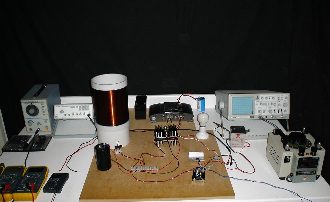
This is the circuit that keeps fusing the transistors.
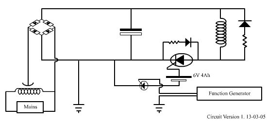
Here you can see the new Alloy tube to hold the magnets in place
when the SQM is ready for testing.
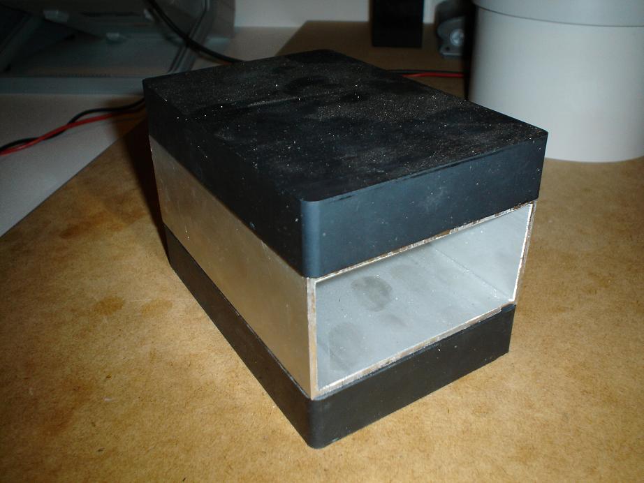
This is really cool. Magnaview. This material is a thin sheet
of plastic film that shows the magnetic field of the magnet. These Pictures are
of virgin magnets that have had no attempt to change their properties. I am hoping
the Magnaview will provide some evidence of change in the magnets when the conditioning
of the magnets is achieved.
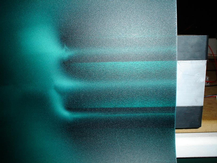
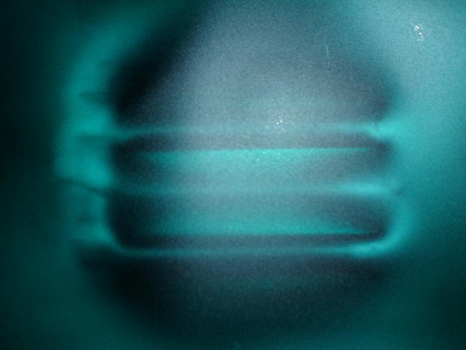
With some organisation, these experiments are now starting to
get a professional look to them.
|
|
13/03/2005 5:06:39 AM
|
10/10/2013 5:08:59 AM
|

|
Edit |
Details |
Delete
|
|
Floyd "Sparky" Sweet - VTA Replication Project
|
Lester Hendershot had a, visually looking, at the Magnet Clapper arrangement, similar device to Floyd Sweets early SQM or VTA..
|
|
|
Hi Everyone,
Visually looking Floyd's early devices were similar
to the early Hendershot device:
Floyd Sweets VTA Gen 1:
Notice the big sponge under the VTA.
|
|
|
13/07/2008 5:11:53 AM
|
10/10/2013 5:11:53 AM
|
|
Edit |
Details |
Delete
|
|
Floyd "Sparky" Sweet - VTA Replication Project
|
Today I have dedicated a much better effort to explaining my last theory Update. It is very interesting to challenge Science and most would say you are crazy to challenge Science. My answer to them is the whole point of Science is to challenge the current theories. A hero of mine, Burt Rutan, said "the point of research is to do something that half the population think is impossible".
|
|
SQM Replication Project Update 14-04-06.
Hi Everyone, I am going to go into
more detail about my theory from the last update. I have had lots of emails with
questions and all of them very good questions to. My explanation may not have been
the best. Mr Bearden has, to my satisfaction, solved the source charge problem.
In all of science the rule of opposites attract is solid. Even in Marriage the same
seems to be true ;O). If we look at magnets, like poles repel and opposites attract.
The same is true for the charged particles in the atom and even charge in a battery.
If we imagine a battery in the below image of Mr Bearden's source charge diagram,
the battery's charge flows from the Positive plate and thus to the Positive Terminal
and out through the wire into the circuit and returning to the negative terminal
on the battery and thus the Negative plate. Charge separation is a chemical force
and in the battery separates the charge back in the same process again. To complete
the circuit Electrons flow through the wire to power any loads (Load could be a
light bulb) that are attached to the circuit. In this case the Electrons are Positively
Charged because they are flowing from the Positive Terminal of the battery.
Source Charge Problem Solved by Mr
Bearden:
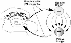
Now if we imagine the Atom. The Electrons
are orbiting the Proton of the Atom, a bit like the Satellites orbit the Earth.
The Electrons are Negatively Charged in the Atom and not Positively charged like
in the Battery scenario above. At the centre of the Atom there are Protons and Neutrons.
Protons are Positively charged, like the Positive Terminal in the battery Scenario
above. Neutrons have no charge and thus the term Neutron. In the case where the
Negative Electron orbits the Positive Proton and the Neutron the thought popes into
the mind "Well the Electron should collapse into the Proton because the Proton
is oppositely charged to the Electron (Opposites Attract) and cease to exist because
the Proton is supposed to be the Anti Particle of the Electron." In other words
the two particles should anile ate due to particles and anti particles colliding.
Well they don't and it is not yet explained by Scientists why they don't. I have
a pretty good idea why they don't collapse.
The Electron is supposed to be responsible
for chemical binding, this means that Atoms bind together and creates Molecules.
You would have seen Chemistry molecule structures.
This is a Hydrogen Molecule:
So Molecules are made up from Atoms.
At this point it is very important
to ask the question "Where the Atom keeps getting its energy from". It
is Perpetual.
The only "Machine" we
know of in the Universe that is in Perpetual Motion.
Now if we think about how the binding
of an Atom is going to work (Keeping in mind the opposites attract and likes repel
rule). So it must be only down to two Processes that account for Binding the Atom.
One force must be gravity?, Mass of the protons attract each other. Mass is the
same but Protons are much more dense than the Electron. At school we were taught
Mass attracts Mass. So this means that the Protons of an Atom can sit in a close
vicinity but the Electrons of each Atom must not collide with the Proton of each
Atom and the Electrons should repel each other. Gravity in an Atom is supposed to
be the weak force though. The attraction of electrons to the opposite Atom's Proton,
remember likes repel and opposites attract, could have some affect but the higher
orbits of the Electron should prevent this attraction by cancellation of the attraction
force because likes (The Electrons) Repel. Now only one possibility is left.
It is the "EM non Observable
Flux". It must be fairly obvious now that everything is not playing Our Science
game here so we must change our Science game to suit what is really going on. In
Prof Dr.-Ing. Konstantin Meyl's book "Scalar Waves - First Tesla Physics Text
Book" Nutrino's are the driving force behind everything in the Universe. I
believe the Non Observable EM Flux is Nutrino based and this is a Universal force.
The Electron is the only particle capable of collecting Nutrino's and transforming
into Negative Electron Flows. A little bit like a black hole pulling apart a star
and the black hole can spit out streams out the ends in a jet form the Electron
creates an organised flow of Nutrino's if the term is ok, "The Electron Feeds
on the Nutrino's". This creates a charge flow from the Electron to the Proton
exactly like in Mr Bearden's source Charge solution above and an adoption of it
in my Diagram below. The Electron is a light weight particle. This continual flow
is the force of stability needed for the Atom. The energy ejection acts like a jet
engine keeping the passenger jets up in the sky for our safe travel to other countries
for holidays etc...
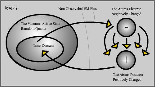
So The Atom is explained, maybe a
few minor details need to be covered but the general working of it is explained.
The Electron is Collecting or Feeding on Nutrino's and as a result of energy transformation
the Electron is ejecting Negative Energy Flows out from themselves. Same as in the
Above Diagrams. Normally these Negative Energy Flows are captured by the Positively
charged Proton. Protons being positively charged would just dissipate the energy
the same as a Battery destroys the dipole in a conventional circuit. See Mr Bearden
web site for more information on destroying the Dipole in conventional circuits.
Some Information Here.
So you are saying what has this information
possibly got to do with the SQM. The SQM takes these Electron flows and uses them
directly. We are trying to cancel the interactions of the Proton and collect the
Electron Flows by giving the Electrons a path to cancel the Positrons effects of
ejecting positive power. Mr Floyd Sweets words were: "A motionally induced
E-field is actually created within the space occupied by the moving magnetic flux
described above. This field is present therein, whether or not a conductor is present
in the space." This is the power house of the SQM or as some like to say the
VTA. The Diagram below shows the path of the collection process.
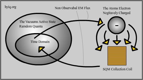
To explain the process: Nutrino's
are captured by the Atom's Orbiting Electrons and the Electrons Negative Charge
flows are captured by the SQM's collection coil. From the Collection coil Negative
power is used in the circuit to power loads and in turn converted to heat or light
as part of the normal conversion processes and then the Negative Electrons remaining
return to the opposite terminal of the Collection coil. To be able to achieve the
Electron Flow Collection A Motional E-Field is needed and the Motional E-Field is
between the Moving Magnetic Lines of Flux in the Conditioned magnets.
Lots of information contained in the
Dirac Sea documentation I have read is in my belief sketchy. Some makes no sense
and sounds almost not true. In my reading of this literature I kept in the back
of my mind the fact that Paul Dirac had all the theory and equations before the
Proton was even discovered. Another particle was thought to be the factor behind
the Negative Energy parts of the equations and not the transformation theory's I
have presented here today. The Proton was predicted by Paul Dirac and was formulated
as an Anti Particle of the Electron which is true but from what we know the Proton
is not producing any Negative Energy at all. We know the Proton is Positively charged
so in my opinion it simply can not support Negative Energy. Paul Dirac saw
Positive power and only factored Electrons flowing in a wire in a positive power
formation.
Well more coming soon as always.
|
|
14/04/2006 5:13:55 AM
|
10/10/2013 5:15:33 AM
|

|
Edit |
Details |
Delete
|
|
Floyd "Sparky" Sweet - VTA Replication Project
|
More good news, I have got resonance on top of the big conditioning coil now after purchasing a 15 cell car battery. More power to the amp has increased the field slightly but it is still not as strong as Mr Sweet had it in the video. I am going to put this down to magnet depth and better production of the magnets now with higher field strengths.
|
|
SQM Replication Project Update 14-05-05.
This is the first ever PUBLIC replication
attempt of the SQM Conditioning process that is in the SQM video with Mr Sweet and
Mr Bearden. Although not yet successful some great results did come out of the attempt.
The new magnets did give different results compared to the last magnets that I broke
which is very interesting. I hope very soon to have a small output even if it is
not more than the input.
I am still close to the first attempt of conditioning the magnets but a few small things I am not yet happy with:
1/ Time to discharge the capacitor is still causing the SCR/Thyristor to latch.
I am still thinking my direction here may not be right. I have briefly tested the SCR oscillator circuit with no success. This is what I need. Capacitor to discharge and to turn off the SCR with back EMF. This could be a single discharge of the capacitor but is more likely to be a discharge in oscillations other wise this does not explain the bulb in the video oscillating in brightness.
2/ Increase if possible the resonance affect at the top of the large coil, the blade is waving or oscillating but is is fairly lightly oscillating.
There is a bit of a delicate balance in this setup for the conditioning. Tuning and adjusting after time will give the desired results here and I hope we get the results with the magnets after this is all done. I am thinking more and more that it will. I found these quite good articles about magnets also there is some mentions of instabilities of the magnets and that's what I think we are going after. Click Here.
Something I am finding interesting is the amount of pages on the net that have been taken down when you search for "Spin wave instability magnon distribution for parallel pumping". Interesting ;o) Lucky I have a few books about this phenomena.
|
Here you can see the pulse to
the conditioning coil. It is an ac pulse which is a result of the RxC time constant.
The Resistance times the Capacitance is the time constant. In this case the Capacitor
is 1500 UF and the Resistance of the Conditioning coil is 10.7 Ohms. So this Discharge
is 16.05 mS. This is about 62.3 Hz. The Math is simply 1000/16.05=62.3 Hz.
The best page on the net to work this
out is http://www.cvs1.uklinux.net/cgi-bin/calculators/time_const.cgi.
The page for the magnet supplier
I am using is http://www.magnet.au.com/.
|
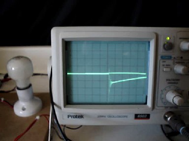
|
This picture didn't really come out
as good as I would have liked but nearly shows the zero crossing of the 60Hz pulse.
I will get a better one and replace this one.
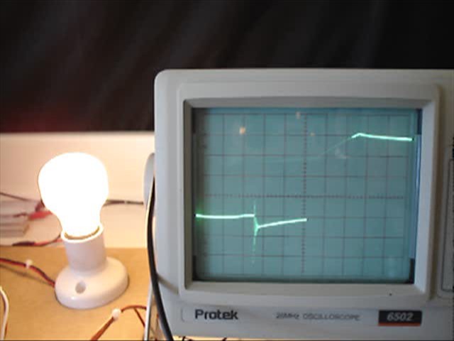
These are some documents I have
been sent by Robert Michaels, about magnetics. This is old school physics that is
very hard to find these days. Thanks Robert.
|
|
14/05/2005 5:20:28 AM
|
10/10/2013 5:21:42 AM
|

|
Edit |
Details |
Delete
|
|
The MEG Replication Project
|
Early tests show promising results. Although my measurements may have room for errors things are looking promising.
|
| |
The MEG Replication
Project by hyiq.org
Please Note: The MEG
is a Patented Device. hyiq.org has been granted permission for this
Replication by The MEG's Inventors.
|
I have
seem some fairly good results on this configuration. In
early tests, although there is room for measurement error,
I have measured from 98% to COP = 1.137 in the MEG's performance.
It takes some adjustment to get this. My Actuator coils
are 20 turns of AWG 18 (1mm Wire) and my Power coils are
AWG 12 (2mm Wire). My Wave on the output is not like the
MEG Patent waves that were shown so as yet I have some work
to do.
Test 1:
Load 18 watt globe.
Input:
7.4 Volts
1.9 Amps
14.06 Watts
Output:
13.11 Volts
1.22 Amps
15.99 Watts
COP = 1.137
I have
a Square wave driving the MEG at the moment and have not
used Decay and Rise time control yet as Tom Bearden said.
The Capacitors you can see in the circuit to try to get
the Rise and Decay Time adjustment have not been tuned yet.
I think my actuator coils may not be optimal. I think I
may change them soon to see if I can get a better result.
My tests so far are not in line with the MEG Patent and
this result may be due to the transients that are visible
on the scope, although small this could be where the extra
input is coming from.
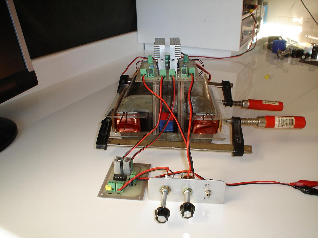
This
early result took some work to get. Most of the tunning
I did I saw a bad result and a lot of energy is wasted in
the input coils when not tunned right. I still have a long
way to go before the MEG has been replicated correctly.
|
|
|
|
14/09/2009 5:46:18 PM
|
10/10/2013 5:47:34 PM
|

|
Edit |
Details |
Delete
|
|
Floyd "Sparky" Sweet - VTA Replication Project
|
Hi Everyone I have decided to publish the information I was given as it is very important and think a no answer is a yes. If the Author would like it removed please email me. I have removed the name of the Author until I hear from the Author. I have also put a link up for a good java applet to show the E-Field. More experiments are continuing and I will update the SQM page soon.
|
|
SQM Replication Project Update 15-05-05.
Hi Everyone, I have not received a
yes or no about permission yet to put this information up but I am going to do it
any way. It is very important and if the author would like it taken down then the
author can let me know and I will remove it right away. I apologise if this causes
any problems to the Author but I must say good work and this sounds like the closest
replication thus far of the SQM. I also have found a good web site that shows the
E-Field in a java applet:
http://www.cco.caltech.edu/~phys1/java/phys1/EField/EField.html
The Motional E-Field.
This is one of my most interesting
projects that I have kept private. While experimenting for several years on this
project, I decided to release what information I have concerning this extremely
exciting subject. The experiments I will explain could Kill you. Use Extreme caution.
You have been warned, proceed at your own risk.
Lots of folks have tried in vain to
build a machine that exploits the Motional E Field. The problem is a basic understanding
of HOW it works. Notice, I did not say why it works. I don’t have a clue as to WHY
it works. I have read everything I could find on the subject, it is vague on what’s
out there about it. I will leave WHY it works to Bearden, Sweet, Kaluza-Klien and
others who profess to know this. I do recommend reading "Nothing is Something"
by Floyd Sweet found with a good search program. But even then he is trying to explain
where this mystery potential is coming from, instead of explaining how to actually
build a device to produce it.
A normal wound coil has induction.
A Bifilar coil connected in reverse-Parallel {Ends Tied} has very little. We will
use both in a device to exploit the MEF. The experiment will be just that, not a
full time working device ready to power your house or car. Purchase {3} rolls of
24 gauge at 100 feet each magnet wire. I use the GC brand part# L3-612. Gather {2}
empty plastic spools with a 1 inch bore. The GC brand comes on these 1 inch bore
spools, very handy. Take {2} rolls of the 24 gauge wire and wind them on a empty
spool. We are making a bifilar coil. Take your time and wind it carefully keeping
the wires together as you wind. You need good balanced bifilar coil. Make sure the
wires are the same length, 100 feet. When you get through, clip the ends equal and
tie them together. Now test your bifilar wire. It must NOT conduct any electrical
potential and or current. Hold it next to a spinning magnet assembly of sorts with
a good meter set on AC. Nothing.... it must not conduct anything, this is very important.
The bifilar coil will be your pick up coil, but NOT as NORMAL electrical conduction.
Take your last roll of wire and leave it on the spool and we will use it as the
exciter coil. These coils have no cores, and you will see why later.
Find or purchase {2} ferrite magnets
2" x 6" x 1" will do. We are only doing an experiment.
You will not have a continuous output,
so go this route first. Do not use Neo's, their lattice domains are very tight.
You will have to demagnetize these magnets to about 10 to 20 gauss. How you do it
is up to you. One can wrap the magnets with magnet wire and dump cap voltage against
the fields, or use heat. This is common, so I won’t go into that procedure here.
Once the magnets are demagnetized, we need to treat them. We need to impress a 60
Hz field in the now loosened domains of the magnets. Wrap the magnets separately
with 100 feet of #19 or #20 wire each. Wire these in series and connect them to
a veriac on the lowest level. Go do something else for 2 or 3 hours. You can build
conditioning coils on forms that slide over the magnets for easy removal and installation.
After 2 or 3 hours remove the coils and check the magnets with a scope. You should
see a weak 60 hz signal on the magnets. Carefully place the bifilar coil and the
exciter coil between the {2} magnets. Space them as far apart as possible without
the spools hanging off the edges of the magnets. use plastic ties to keep them in
place.
Connect the Exciter coil to a generator
at 8 to 12 volts at 2 to 3 ma at 60hz. Place a load across the bifilar coil, such
as a light. See if the bulb will flash. If it does, place more bulbs in line with
the load. It may even blow the bulb. This field is regulated by load. You may have
to experiment with the exciter voltage to get the effect to occur. All one wishes
to do is vibrate the magnet. do not overdrive the magnet with the exciter voltage.
This will not last long, the magnets will loose the 60Hz signal. Perhaps Barium
ferrite IS needed to keep the 60hz signal or the whole design is not shielded properly
or it will always run down. Barium has high electron emissivity and promotes electron
scattering when excited. The point is: Something of the electrical nature lit the
bulbs from a non-conductive coil. The bifilar coil was not connected to anything
but the bulbs placed between the {2} treated magnets.
Now, HOW it works. As current flows
through a wire the electrons act like magnets when they MOVE. Now if they don’t
move, they just have a electrical field around them. If we move this current through
the bifilar coil, the magnetism cancels. But moving the electron magnetism will
actually add. The magnet domains have been loosened. Their domains are not locked
in a position they can shuttle some what within the structure. But they still have
a very small amount of magnetism. It is like billions of small magnets vibrating
about the domains because of the 60hz exciter coil. They also have a 60hz signal
that we supplied to the magnets. Because they have a slight charge on top of being
small magnets the E-Field will manifest into the bifilar coil. But this is not the
normal conductive current. In fact any normal conductive current abounds, it will
cancel the effect. This is the reason the bifilar coil must be made so carefully.
You MUST have the least amount of induction in your bifilar coil as possible. This
is the reason I use no core. I want a small exciter signal that does not interfere
with the bifilar coil, so the exciter coil has no core either.
All the exciter coil does is vibrate
the domains which have the 60hz signal placed on all those billions of atoms already
that are very slightly magnetized in the domains. Moving a electrical charge against
another charge by separate wire cancels the magnetism in both wires and adds.
This is the Motional E-Field.
3-1-03
I have done some brief experiments
to try to verify this work but not yet had any success. I am very excited about
this and will continue in this area as well as the conventional video data from
Mr Sweet and Mr Bearden.
I also got this Email that is very
interesting and sheds some light on magnet conditioning:
I was looking at your website especially the John Bedini and Tom Bearden inputs. Peter
Bruce Quoted Sweet as follows regarding magnet conditioning during a discussion:
"Searl activated his magnets in a fluxgate
furnace in a manner different from Sparky's method".
About Searl's method of magnet conditioning here is a description sent to me some
15 years ago by the late Gunnar Sandberg who met and investigated Searl's claims:
"The Magnetisation method used by Searl : The coil
used by Searl to magnetise molded cores was originally intended for and used to
demagnetise (degaussing) turbine shafts and generator shafts and consisted of approximately
200 turns of heavy electric copper wire normally used for connecting electric cookers
to the mains. The magnetising current was 180 amperes and supplied by a westinghouse
three phase mercury rectifier. The on-off cycle lasted seconds rather than fractions
of a second.
Based on what can only be described as intuition, Searl
suggested that a second winding be added to the existing magnetising DC-Coil and
connected to an AC source. This proposition created heated discussion amongst his
fellow workers as to the effect of such a magnetising method. The general view was
that the magnetic field created by an alternating current would partly cancel the
magnetic field created by the direct current and make the coil less efficient. However
Searl suggested that the existing RF signal generator in the laboratory
should be used as an AC source; this would prevent cancellation of the DC field.
This idea was met with even greater scepticism as the current supplied by the signal generator
would be minute and have an insignificant effect on the magnetising process. Searl
persisted however with his views and eventually suceeded in winning his manager's
approval. Searle can remember his manager carrying out certain calculations concerning
the design of the AC winding which were beyond Searl's comprehension at the
time, however based on fundamental electrical engineering, it can be assumed that
the calculation involved resonance and characteristic impedance determinations in
order to avoid shorting out the signal generator".
This suggests that the Sweet's idea came from hearing about Searl. Also Searl used
bonded cores rather than sintered material. Seale magnetised roller had tracks of
n-s-n poles all the way round.
Going
back to Sweet He also says "Magnets are spaced 2" apart in traction mode
The excitation coil is inside the and is bifilar and wound to cause space stress
in the magnets. The exciatation is very weak but apparently moves the traction flux.
The kernal flux of the conditioned magnet is cancelled out at least 1" from
the pole faces, the central airgap flux is made to appear and dissappear in step
with the space stress caused by the excitation coil."
The bifilar coil idea seems to originate from Hooper's motional-field experiments.
Thanks Mike for the excellent Info.
|
|
15/05/2005 5:27:56 AM
|
10/10/2013 5:27:56 AM
|

|
Edit |
Details |
Delete
|
|
Floyd "Sparky" Sweet - VTA Replication Project
|
After several months of thought about my experiments a solid theory has evolved and it is getting exciting to know that this is where everything is sitting in place very well.
|
|
SQM Replication Project Update 15-08-05.
Theory after two
months of thought about past experiments.
What we know about
the SQM Conditioning setup Mr Floyd Sweet had setup in the video with Mr Bearden.
There are two coils,
one Resonant Coil inside the bigger Conditioning Coil, at the bottom. The Resonant
coils height to the top is roughly ¼ the way up the Conditioning coil. The Resonant
coil is driven by a 100 Watt Amplifier and a Wave Tek Oscillator is the input signal
to the Amplifier. The approximate frequency the Oscillator inputs is around 11 Hz.
The Conditioning
coil is driven by a capacitive discharge circuit. In this circuit there is a SCR,
a Capacitor, with a rating of 1600uf and 250 Volts and there appears to be a small
circuit with what appears to be some Capacitors and resistors in it. This Circuit
appears to be driven by a Triac and can be adjusted up and down in voltage and possibly
in frequency this is an assumption because there is a Light bulb attached to this
circuit and it appears to flicker at different frequency while being adjusted by
the Triac. The appearance of a frequency in the flashing of the bulb could be the
capacitor charging and discharging with the power fluctuations when turned up and
down by the Triac. For example: If the Triac was turned down the capacitor would
take longer to charge and the discharge would be of a low value thus the light would
dim. If the Triac was turned up full the Capacitor will charge much quicker and
the discharge would be of a higher value and thus the light would be brighter.
The Power from
the wall socket in the United States is 115 Volts and in the circuit there appears
to be a Bridge Rectifier with at least one extra wire coming out than what normally
would. So there is two wires going in as AC, two wires coming out as DC and an extra
wire coming off one side of the AC plug. As far as I know Triacs are AC devices
and don’t work on DC because of the Sine Wave signal where as DC is not a Sine Wave.
This would indicate
there is AC Current in this circuit as well as DC.
Important: A SCR
when turned on will latch on until the current is turned off or the Gating current
is reversed. In past experiments I have used another coil to cut off the SCR when
it is on by using the back EMF to switch off the SCR. This other coil was the secondary
Resonant Coil which was on the outside of the Conditioning Coil.
We know two frequencies
that Mr Sweet used, the Resonant frequency is around 11 Hz and the Frequency of
60 Hz is what we are trying to impress into the magnet. The mains frequency is between
50 and 60 Hz and if AC was used in the circuit it could be used to turn off the
SCR and Switch the SCR also. This would require an extra coil on the Conditioning
coil and the small circuit with capacitors and resistors in it.
Important: The
Capacitor will discharge only 30 times a second if the mains power was at 60 Hz.
The other half of this time the current to the capacitor would be off and the capacitors
charge rate would be nearly 0. This in itself would help turn off the SCR.
A thirty Hz pulse at right angles to the magnet would create a sixty Hertz oscillation
to the magnets field but keeping the oscillation steady and lasting would be tricky.
With magnetics the major rules have a very strong relationship with a force at right
angles or a field at right angles. Just check out the right hand rule.
Click Here.
The circuit would
bring two states to the magnet, the AC signal at right angles to the magnet would
create an AC oscillating magnetic signal with some strength to the oscillation.
At the bottom of the AC sine Wave the DC Capacitor would be discharged in alignment
of the AC Wave and give a strong jolt to the magnet at right angles to the magnet.
This would be 30 times a second so the capacitor must be Charged, and discharged
enough so the AC Coil could turn off the SCR and that would be another reason why
only 1600uf was used by Mr Sweet with a coil resistance of around 10 Ohms.
The trick, I believe,
to making this work is with the magnets and a very fine line in the voltage discharged.
The magnets MUST be Isotropic preferably Barium Ferrite. There would be a
very fine line with the discharge, not enough voltage and you would see no results,
too much voltage and you would make a permanent change to the magnetic field and
damage the oscillation you are trying to put into the magnets. This could be fixed
by just remagnetising the magnets again. Isotropic means that the magnet in this
case can display properties in all directions, Anisotropic means the magnet can
have properties in only one direction.
With this theory
everything fits, Mr Rosenthal when he said the Zero Crossing is the trigger. Getting
a 60 Hz oscillation and not having a complex switching circuit in the Video. Using
a Triac as the switching for the SCR.
Remember, Mr Floyd Sweet did quote
in his paper "Nothing is Something", "The fundamental magnets have
been broken free of their binding forces which constrained them to be steady state
single pole uniform magnetic flux devices."
My Magnets will
be here soon and I am very excited to try this theory and think this is what I have
been aiming for all along. The theory makes perfect sense and should work by all
accounts. It is very exciting to have this so clear in my head and I am very confident
this will work and we will finally have what we want. A source of clean cheap renewable
Energy.
|
|
15/08/2005 5:30:19 AM
|
10/10/2013 5:30:19 AM
|

|
Edit |
Details |
Delete
|
|
Floyd "Sparky" Sweet - VTA Replication Project
|
Medusa has taught me a few things in its evolution. I have thought about the device and what I was trying to achieve and it dawned on me, "It is getting too complex". Coming back to basics, I thought well Floyd was a transformer expert so what if he was able to do what he did with a few Transformers?
|
|
SQM Replication Project Update 16-04-07.
Coming back to basics
Medusa is too complex for the average
Joe to replicate and really I knew I could do the same thing with more Simple hardware.

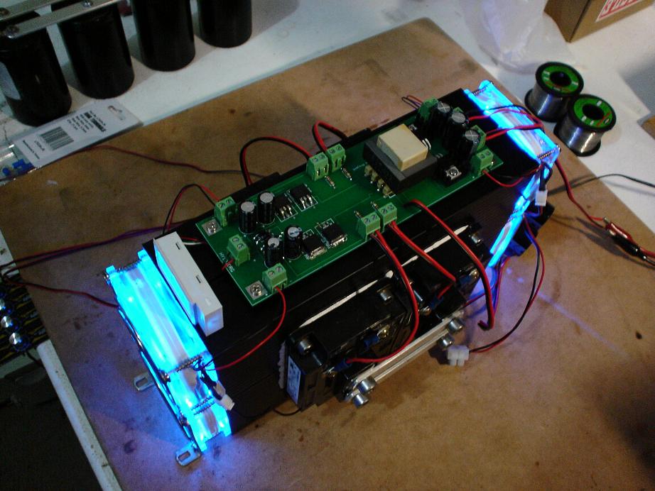
Looking more like Floyds original
setup. Still a work in progress and a bit messy... As you can see, I have rebuilt
the Conditioning coils. Making it easier to access one winding at any one time if
I need to adjust the Coil itself.
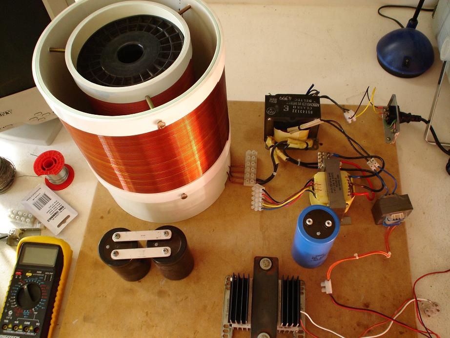
I will update this picture when I
get it closer to a point where it is working.
Well more coming soon as always.
|
|
16/04/2007 5:33:06 AM
|
10/10/2013 5:33:06 AM
|

|
Edit |
Details |
Delete
|
|
Floyd "Sparky" Sweet - VTA Replication Project
|
The VTA Replication Project progresses with some more improvements and some additions.
|
|
SQM Replication Project Update 17-04-05.
A video update has been added today
as well as the pictures below. As you can see I have built the collector coils and
a tickler coil. These are placed inside the SQM and when the magnets are conditioned
they oscillate the magnets and collect the oscillations. This quote is from Mr Sweets
"Nothing is Something".
"The
vacuum triode is a solid state device consisting of conditioned permanent magnets
capable of producing a motional field. This field opens the gate to the Dirac Sea
where negative
energy is able to flow from an into the triode's receiving coils. The coils are
very small diameter
copper wire but are capable of producing in excess of 5 kilowatts of useful power;
this in itself
is a clear indicator that the type of electrical energy provided by the device is
not conventional.
The wire sizes employed by the device would not be capable of carrying such large
currents
without excessive heat gain, however, the triode's coils actually run cooler when
loaded at 5 kW.
The fundamental magnets have been broken free of their binding forces which constrained
them
to be steadystate single pole uniform magnetic flux devices. They are now able to
simply
support mass, as demonstrated with the transformer steel illustration. They can
now easily be
made to adopt a dynamic motional field by applying a tiny amount of excitation.
Specifically,
10V @ 1 mA (10 mW) of excitation at 60 Hz. will enable the coils of the triode to
receive from
the Dirac Sea in excess of 5000 watts of usable negative energy; how much more can
safely be
removed has not yet been determined."
This quote is really interesting.
"They can now easily be
made to adopt a dynamic motional field by applying a tiny amount of excitation.
Specifically,
10V @ 1 mA (10 mW) of excitation at 60 Hz. will enable the coils of the triode to
receive from
the Dirac Sea in excess of 5000 watts of usable negative energy; how much more can
safely be
removed has not yet been determined". This means the
magnets are not in an oscillation until the tickler coil is on and oscillating at
the conditioned frequency.
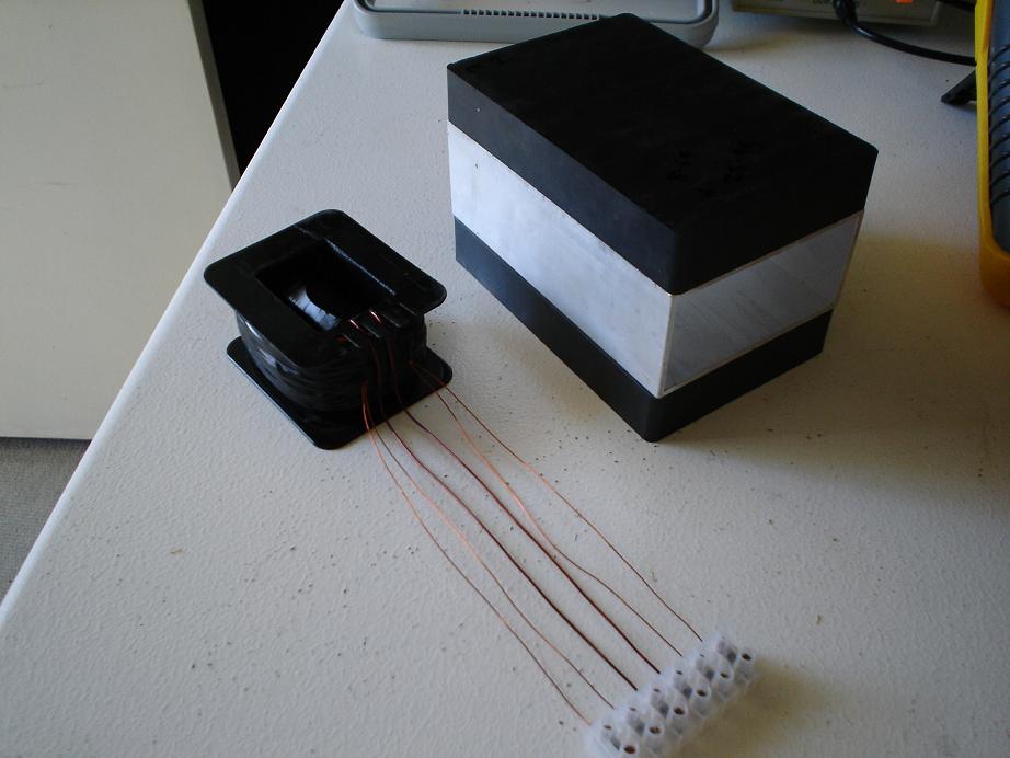
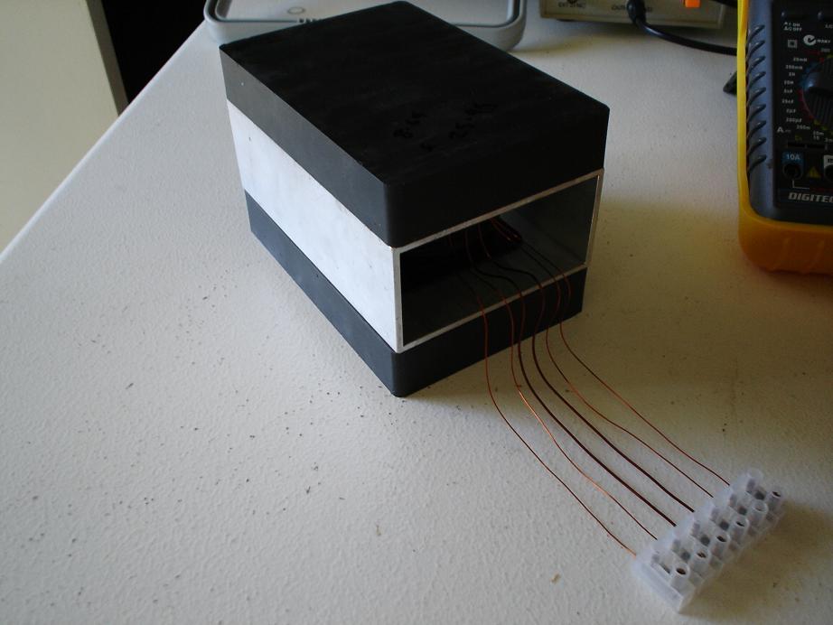
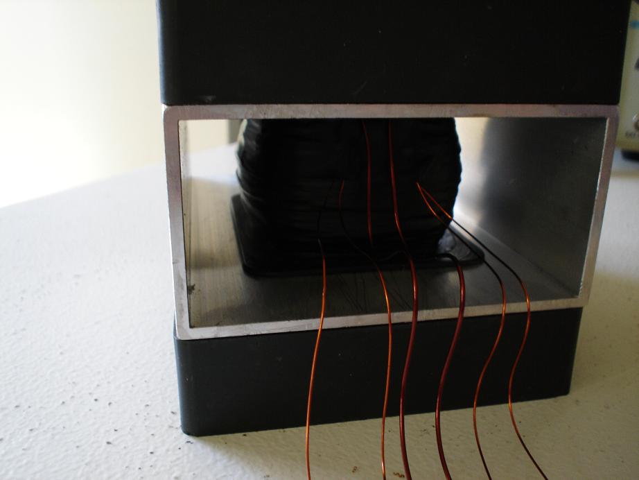
This is the Picture I first used as
a guide to the wave form I tried to first get from the coils.
|
|
17/06/2005 5:38:39 AM
|
10/10/2013 5:38:39 AM
|

|
Edit |
Details |
Delete
|
|
The MEG Replication Project
|
The MEG Replication Project started 17-06-09. hyiq.org is taking on a Replication of the MEG. A dedicated replication project to replicate the MEG of Thomas E. Bearden, Ph.D. James C. Hayes, Ph.D. James L. Kenny, Ph.D. Kenneth D. Moore, B.S. Stephen L. Patrick, B.S.
|
| |
The MEG Replication
Project by hyiq.org
Please Note: The MEG
is a Patented Device. hyiq.org has been granted permission for this
Replication by The MEG's Inventors.
|
Tom
Bearden "One build-up has produced up to 100 times more
power than was input"
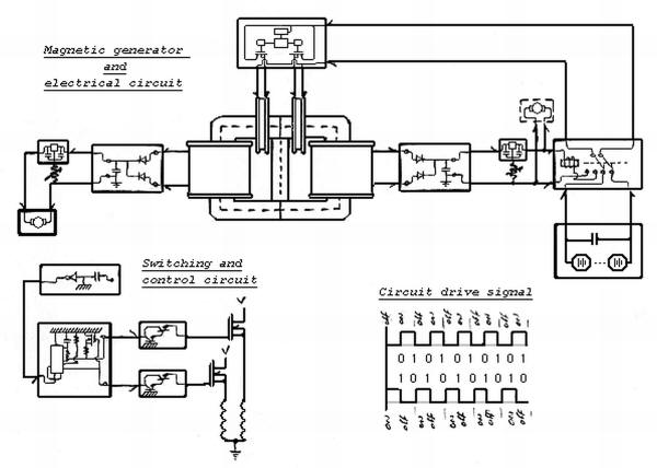
A basic
idea on how The MEG Works.
The MEG has some history. Although patented in 2002 by Thomas
E. Bearden, Ph.D. James C. Hayes, Ph.D. James L. Kenny,
Ph.D. Kenneth D. Moore, B.S. Stephen L. Patrick, B.S. The
MEG has operational characteristics of many other devices
throughout History. Some may disagree with my opinion but
that's all this page is about, my opinion on how the MEG
Works.
Simply put, The MEG is See-Sawing Electromagnetic Flux from
the Permanent Magnet from side to side of the MetGlas Cores.
As the name suggests The MEG is a Generator, just a stationary
one. The actual EMF Generated in the Output Coils is induced
in a slightly different manner than the EMF Generated in
a Conventional Generator, or at least how current theory
says EMF is Generated in Generators. We must remember the
great Michael Faraday only said, we only have to have a
Flux move in relation to the Conductor to generate an EMF
in the conductor.
A Magnet's Flux is made up of several things (called vectors
and potentials), we look at these forces in a manner where
we can define these forces in a manner similar to a River.
This is similar to Electricity, Flow and Current. Flow can
be the amount of water flowing in a River, or Volts in a
Electrical Circuit and, Current, how much force or power
the Flow is travelling at, similar to the Current in an
Electrical Circuit. These differences are defined as the
H field, (Current or strength) and the B Field, (Flow or
volume). Looking at Magnetic, or Electromagnetic Flux is
made simple when viewed in these terms.
To move Magnetic or Electromagnetic Flux requires Force.
In the terms of a River, to stop the flow of a river we
must have a river flowing, equal in Flow and Current, flowing
in the opposite direction to the River we wish to stop.
Like in the Flux-Gate Magnetometers, it is very important
to look at The MEG in two halves. One half on one side and
the other half on the other side. Each side containing a
Power Coil and an Actuator Coil. The Power coil and Actuator
Coil on one side do not match up as a pair. In fact the
Power Coil on one side matches up with the Actuator Coil
on the opposing half of The MEG.
In an idle state, The MEG has equal Flux in each side of
the Core. The idea is that we want to create an imbalance
with our input.
In The MEG we are stopping the Flow of Electromagnetic Flux
from the Permanent Magnet on one side of The MEG at a time,
(this is not entirely accurate, not quite stopping), more
accurately we are re-diverting some Electromagnetic Flux,
from the permanent Magnet, but we are using the opposing
Path for this redirection, the Flux from this path, then
moves into the opposing side of the Core. Because we have
one MEG and two paths, we are simply closing one Path while
having the opposing path open. This makes for greater efficiency's
in the amount of force to move the Electromagnetic Flux.
A Quote from Gabriel Kron:
"...the missing concept of "open-paths" (the dual of "closed-paths")
was discovered, in which currents could be made to flow
in branches that lie between any set of two nodes."
Ok, is Gabriel Kron talking about Electrical Currents or
could it be he is talking about Magnetic Currents? Magnetic
Currents have been referred to before by many people through
history and we have referred to them above. Gabriel Krons
reference to "Nodes" is a
Di-Pole.
One set of two Poles. A Permanent Magnet is a Di-Pole, North
and South Poles.
On our Input we create an imbalance, or difference in potentials
on each side of the cores will give us two effects in the
one action that we input.
1: Flux moved across will induce an EMF in the opposing
Power Coil on the other side of the MEG.
2: Electromagnetic Flux return will create an EMF on the
same side as the DC Pulse was Input.
Thus two actions output for only one action we put in. The
Free action is Action Two. This is Free because Nature is
inputting Energy to bring the system back into its state
of balance, referred to above, equal Electromagnetic Flux
in each side of the core when The MEG is in an idle state.
This is what Tom Bearden refers to as Equilibrium, and how
Nature will bring systems back into an Equilibrium State
for Free.
We have
a few things to think about now. On time of our input. Off
time of our input and also the timing of the clock cycle
or driving frequency of our input. Remembering we need On
time of our input to re-divert the Electromagnetic Flux
into the opposite path and just as important Off time to
allow the Electromagnetic Flux to move back into our then
closed path when our input was On, the same path which is
now Open when our input is off.
The MEG Simulations:
The
Basic architecture of the MEG, Magnet Placement and Actuator
coil alignment and pole directions.
Graphed
Input to the Actuator Coils:
Animation
slowed down so it is visible what's is happening in The
MEG

For
more detailed information please read on.
|
|
The
Core - Metglas® Alloy 2605SA1:
| |
|
|
| |
|
CORE # |
AMCC-1775 |
a
(mm) |
33.0±1.0 |
b
(mm) |
40.5±0.5 |
c
(mm) |
106.30±1.25 |
d
(mm) |
142.00±1.5 |
e*
(mm) |
106.5±2.5 |
f*
(mm) |
172.6+4.0 |
Lm*
(cm) |
39.72 |
Ac*
(cm2) |
39.36 |
Core
Wt.±2%
(gm) |
11466.0 |
Window
Area
(cm2)
|
43.05 |
|
|
|
The material,
known as Metglas, was commercialized in early 1980s and
used for low-loss power distribution transformers (Amorphous
metal transformer). Metglas-2605 is composed of 80% iron
and 20% boron, has Curie temperature of 373 °C and a room
temperature saturation magnetization of 125.7 milliteslas.
An amorphous metal is a metallic material with a disordered
atomic-scale structure. In contrast to most metals, which
are crystalline and therefore have a highly ordered arrangement
of atoms, amorphous alloys are non-crystalline. Materials
in which such a disordered structure is produced directly
from the liquid state during cooling are called "glasses",
and so amorphous metals are commonly referred to as "metallic
glasses" or "glassy metals". However, there are several
other ways in which amorphous metals can be produced, including
physical vapor deposition, solid-state reaction, ion irradiation,
melt spinning, and mechanical alloying. Amorphous metals
produced by these techniques are, strictly speaking, not
glasses. However, materials scientists commonly consider
amorphous alloys to be a single class of materials, regardless
of how they are prepared.
In the past, small batches of amorphous metals have been
produced through a variety of quick-cooling methods. For
instance, amorphous metal wires have been produced by sputtering
molten metal onto a spinning metal disk. The rapid cooling,
on the order of millions of degrees a second, is too fast
for crystals to form and the material is "locked in" a glassy
state. More recently a number of alloys with critical cooling
rates low enough to allow formation of amorphous structure
in thick layers (over 1 millimeter) had been produced, these
are known as bulk metallic glasses (BMG). Liquidmetal sells
a number of titanium-based BMGs, developed in studies originally
carried out at Caltech. More recently, batches of amorphous
steel have been produced that demonstrate strengths much
greater than conventional steel alloys.
The alloys
of
boron,
silicon,
phosphorus, and other glass formers with magnetic metals
(iron,
cobalt,
nickel) are magnetic, with low
coercivity and high
electrical resistance. The high resistance leads to
low losses by
eddy currents when subjected to alternating magnetic
fields, a property useful for eg.
transformer
magnetic cores.
Ref:
http://en.wikipedia.org/wiki/Amorphous_metal
|
Typical Impedance
Permeability Curves & Typical Core Loss Curves:
|
| |
|
General Properties & Characteristics
|
|
ELECTROMAGNETIC |
|
|
Saturation Induction (T) |
|
As Cast
|
1.56 |
|
Maximum DC Permeability (µ):
|
Annealed (High Freq.)
|
600,000 |
As Cast
|
45,000 |
|
Saturation Magnetostriction (ppm) |
27 |
|
Electrical Resistivity (µ-cm) |
130 |
|
Curie Temperature (°C) |
399 |
|
|
|
PHYSICAL |
|
Thickness (mils) |
1.0 |
|
Standard Available Widths |
|
|
Minimum (inches)
|
0.2 |
|
Maximum (inches)
|
8.4 |
|
Density (g/m3) |
|
As Cast
|
7.18 |
|
Vicker's Hardness (50g Load) |
900 |
|
Tensile Strength (GPa) |
1-2 |
|
Elastic Modulus (GPa) |
100-110 |
|
Lamination Factor (%) |
>79 |
|
Thermal Expansion (ppm/°C) |
7.6 |
|
Crystallization Temperature (°C) |
508 |
|
Continuous Service Temp. (°C) |
150 |
|
|
|
|
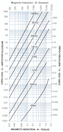
|
B H Curve:
|
|
|
I got my cores
from http://www.uaml.net/.
The Contact there is Vikas. He is very helpful. Please mention
Chris from hyiq.org and Vikas will help you out.
|
|
Aharonov-Bohm
Effect:
|
Magnetic Aharonov–Bohm effect
The magnetic Aharonov–Bohm
effect can be seen as a
result of the requirement
that quantum physics be
invariant with respect to
the
gauge choice for the
vector potential A.
This implies that a particle
with electric charge
q travelling along some
path P in a region with
zero magnetic field ( )
must acquire a phase )
must acquire a phase
 ,
given in
SI units by ,
given in
SI units by
-
with a phase difference
 between any two paths with
the same endpoints therefore
determined by the
magnetic flux Φ through
the area between the paths
(via
Stokes' theorem and
between any two paths with
the same endpoints therefore
determined by the
magnetic flux Φ through
the area between the paths
(via
Stokes' theorem and
 ),
and given by: ),
and given by:
-

-
This phase difference can
be observed by placing a
solenoid between the
slits of a double-slit experiment
(or equivalent). An ideal
solenoid encloses a magnetic
field B, but does
not produce any magnetic
field outside of its cylinder,
and thus the charged particle
(e.g. an
electron) passing outside
experiences no classical
effect. However, there is
a (curl-free)
vector potential outside
the solenoid with an enclosed
flux, and so the relative
phase of particles passing
through one slit or the
other is altered by whether
the solenoid current is
turned on or off. This corresponds
to an observable shift of
the interference fringes
on the observation plane.
The same phase effect is
responsible for the
quantized-flux requirement
in
superconducting loops.
This quantization is because
the superconducting wave
function must be single
valued: its phase difference
Δφ around a closed loop
must be an integer multiple
of 2π (with the charge
q=2e for the
electron Cooper pairs),
and thus the flux Φ must
be a multiple of h/2e.
The superconducting flux
quantum was actually predicted
prior to Aharonov and Bohm,
by London (1948)
using a phenomenological
model.
The magnetic Aharonov–Bohm
effect is also closely related
to
Dirac's argument that
the existence of a
magnetic monopole necessarily
implies that both electric
and magnetic charges are
quantized. A magnetic monopole
implies a mathematical singularity
in the vector potential,
which can be expressed as
an infinitely long
Dirac string of infinitesimal
diameter that contains the
equivalent of all of the
4πg flux from a monopole
"charge" g. Thus,
assuming the absence of
an infinite-range scattering
effect by this arbitrary
choice of singularity, the
requirement of single-valued
wave functions (as above)
necessitates charge-quantization:
 must be an integer (in
cgs units) for any electric
charge q and magnetic
charge g.
must be an integer (in
cgs units) for any electric
charge q and magnetic
charge g.
The magnetic Aharonov–Bohm
effect was experimentally
confirmed by Osakabe et
al. (1986), following much
earlier work summarized
in Olariu and Popèscu (1984).
Its scope and application
continues to expand. Webb
et al. (1985) demonstrated
Aharonov–Bohm oscillations
in ordinary, non-superconducting
metallic rings; for a discussion,
see Schwarzschild (1986)
and Imry & Webb (1989).
Bachtold et al. (1999) detected
the effect in carbon nanotubes;
for a discussion, see Kong
et al. (2004).
Electric Aharonov–Bohm effect
Just as the phase of the
wave function depends upon
the magnetic vector potential,
it also depends upon the
scalar electric potential.
By constructing a situation
in which the electrostatic
potential varies for two
paths of a particle, through
regions of zero electric
field, an observable Aharonov–Bohm
interference phenomenon
from the phase shift has
been predicted; again, the
absence of an electric field
means that, classically,
there would be no effect.
From the
Schrödinger equation,
the phase of an eigenfunction
with energy E goes
as
 .
The energy, however, will
depend upon the electrostatic
potential V for a
particle with charge
q. In particular, for
a region with constant potential
V (zero field), the
electric potential energy
qV is simply added
to E, resulting in
a phase shift: .
The energy, however, will
depend upon the electrostatic
potential V for a
particle with charge
q. In particular, for
a region with constant potential
V (zero field), the
electric potential energy
qV is simply added
to E, resulting in
a phase shift:
-
where t is the time
spent in the potential.
The initial theoretical
proposal for this effect
suggested an experiment
where charges pass through
conducting cylinders along
two paths, which shield
the particles from external
electric fields in the regions
where they travel, but still
allow a varying potential
to be applied by charging
the cylinders. This proved
difficult to realize, however.
Instead, a different experiment
was proposed involving a
ring geometry interrupted
by tunnel barriers, with
a bias voltage V
relating the potentials
of the two halves of the
ring. This situation results
in an Aharonov–Bohm phase
shift as above, and was
observed experimentally
in 1998.
Ref: http://en.wikipedia.org/wiki/Aharonov-Bohm_effect
|
|
|
|
|
|
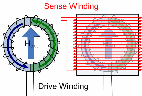
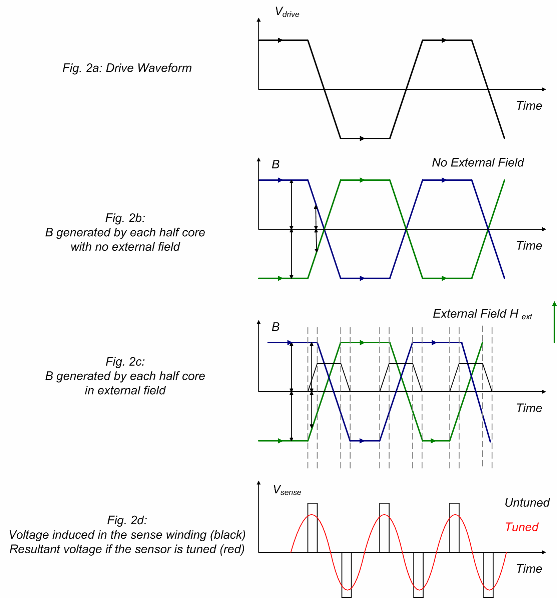
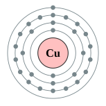


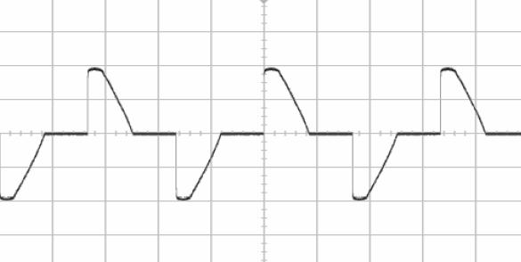
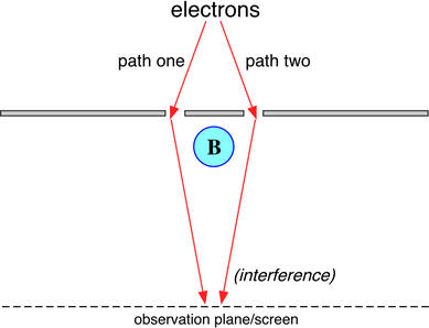
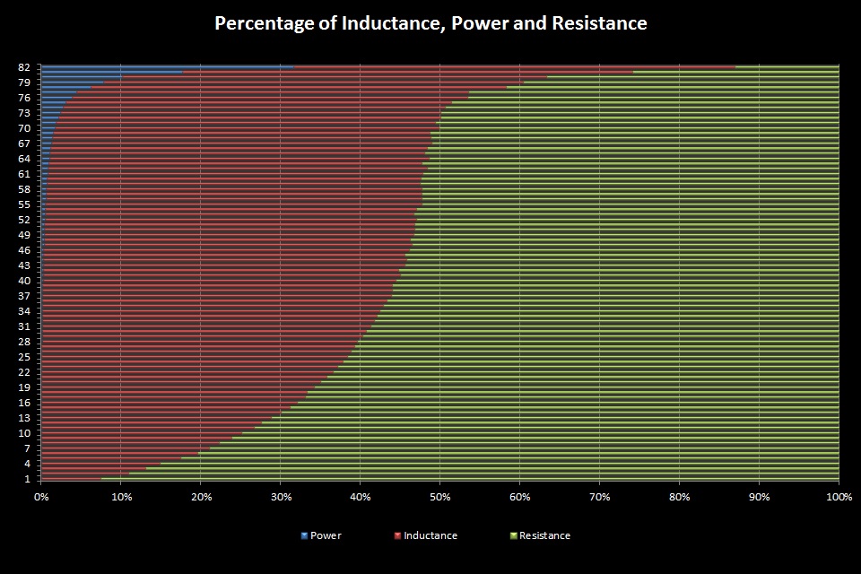
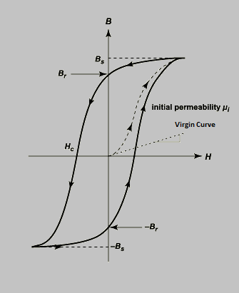
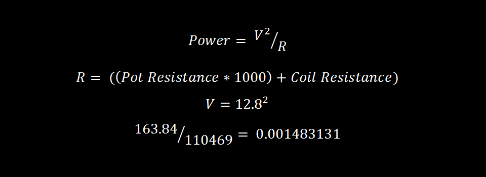
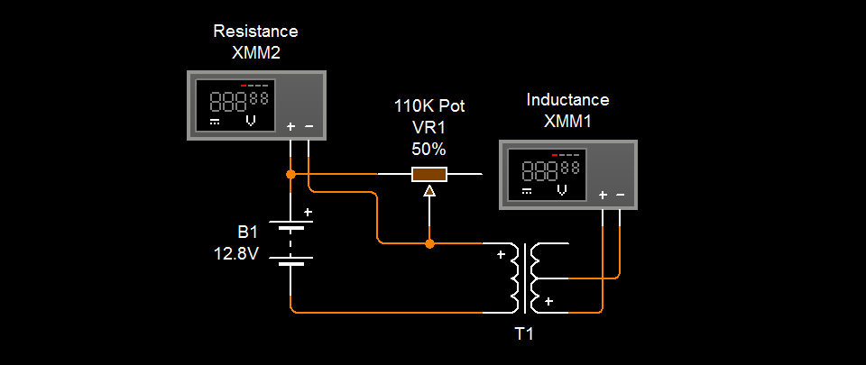
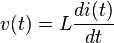
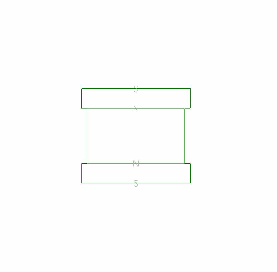
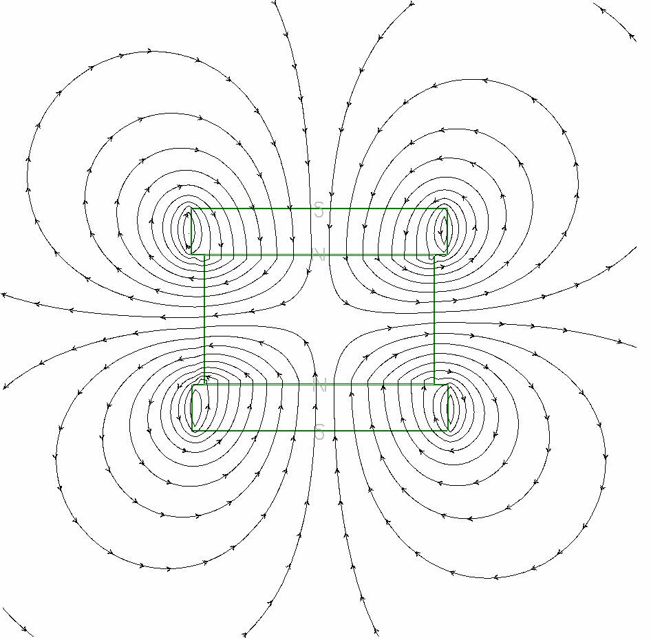
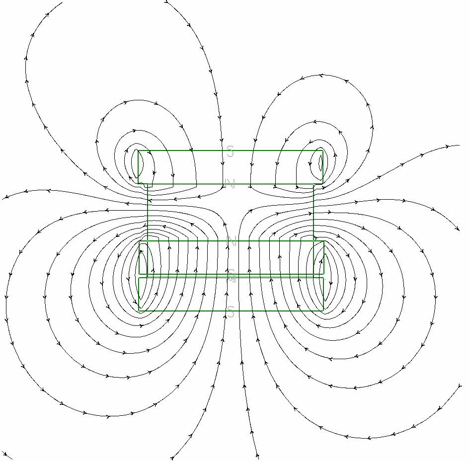
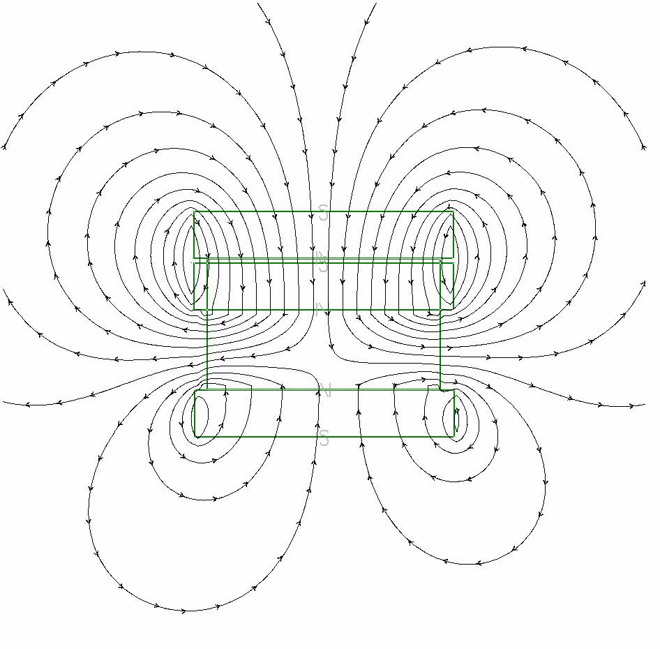
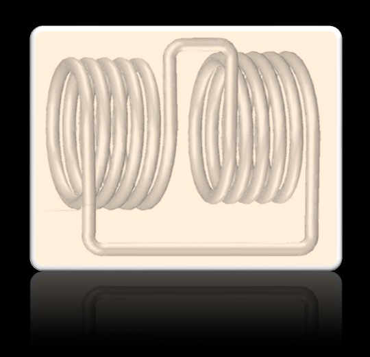
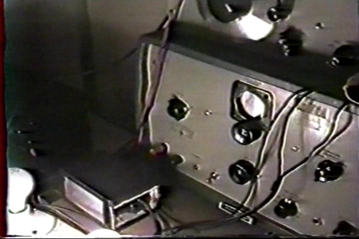
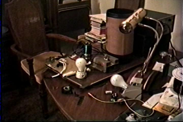
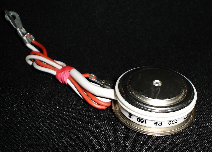
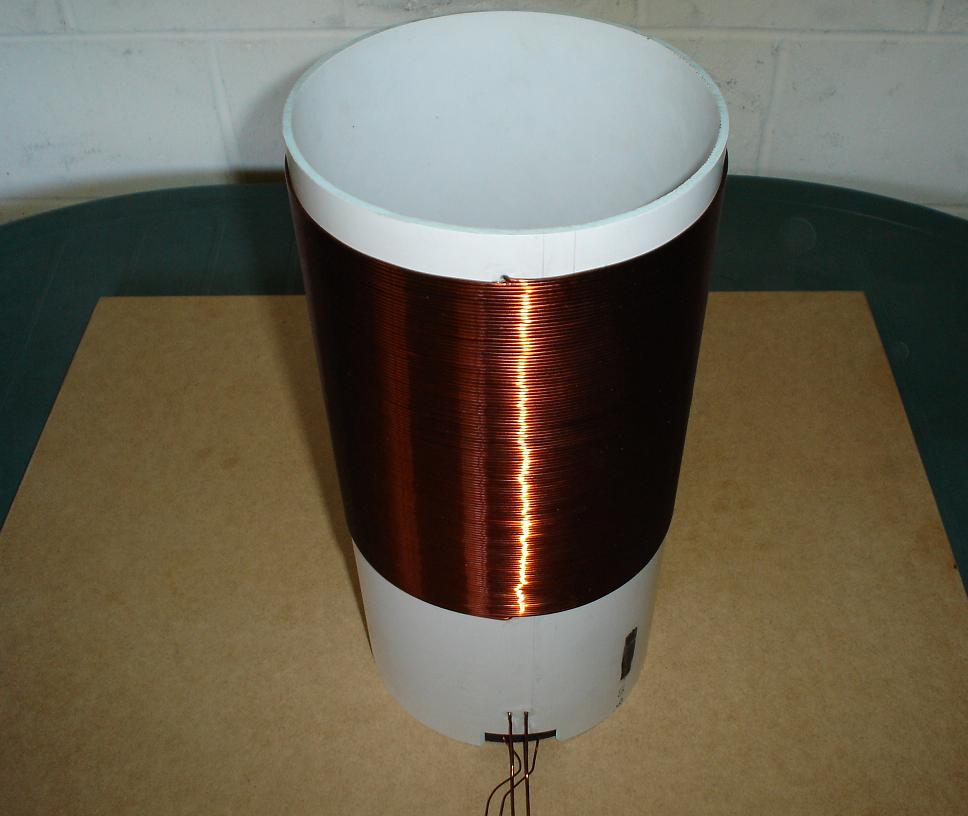
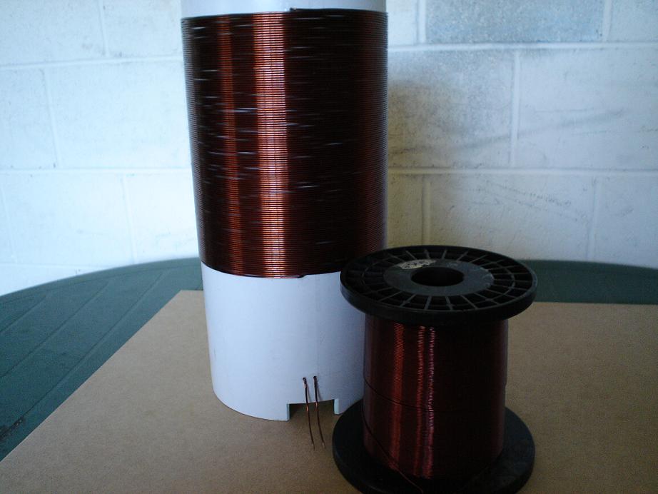
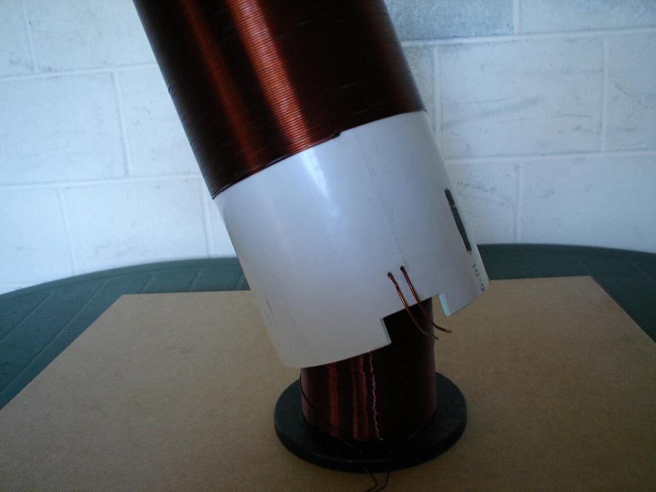

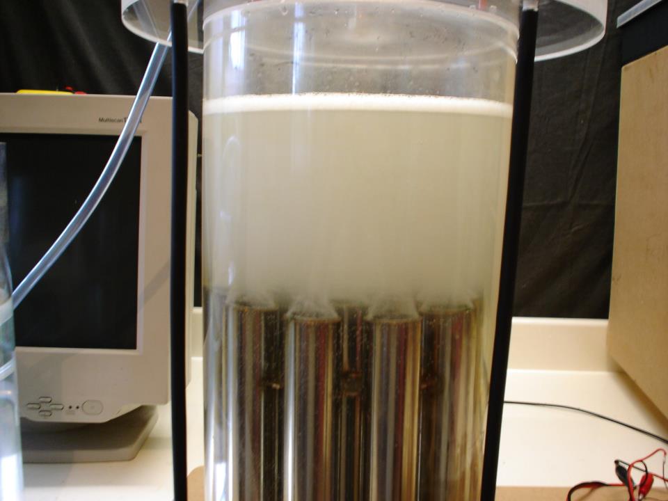
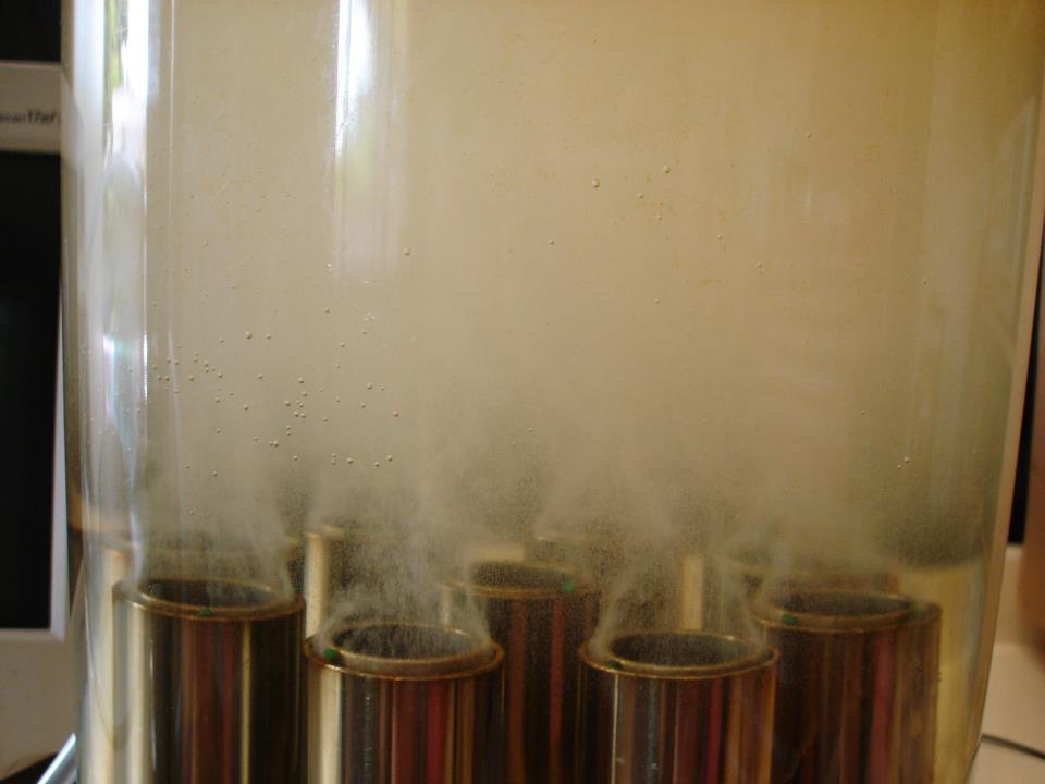
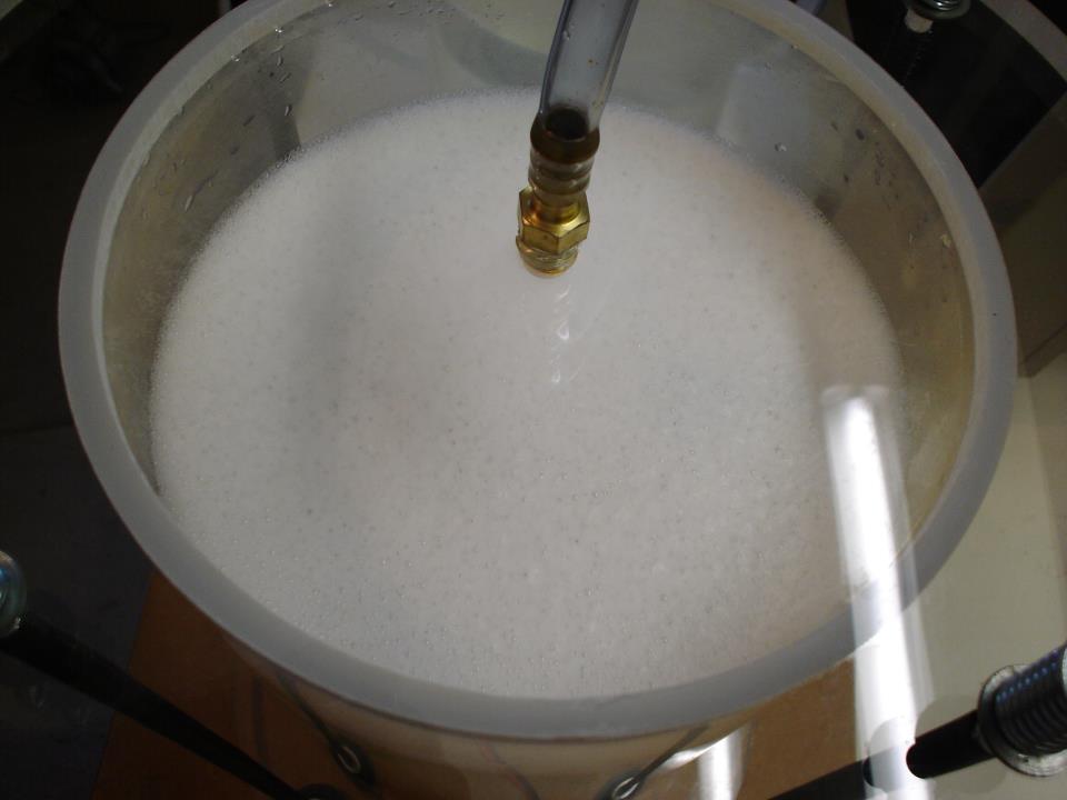
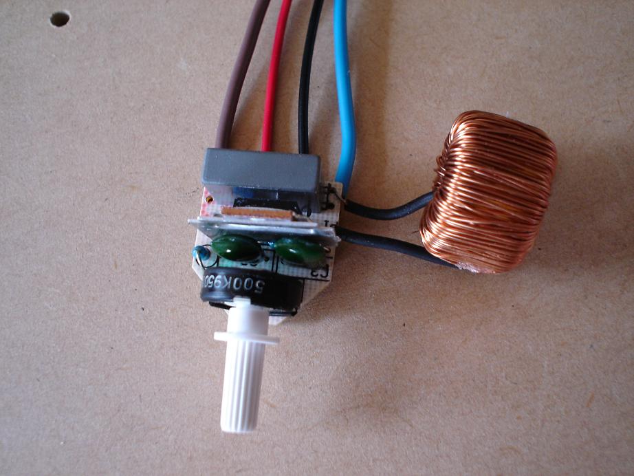
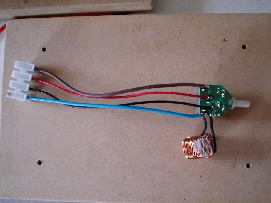
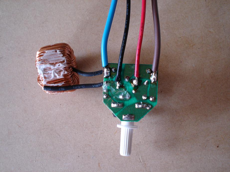
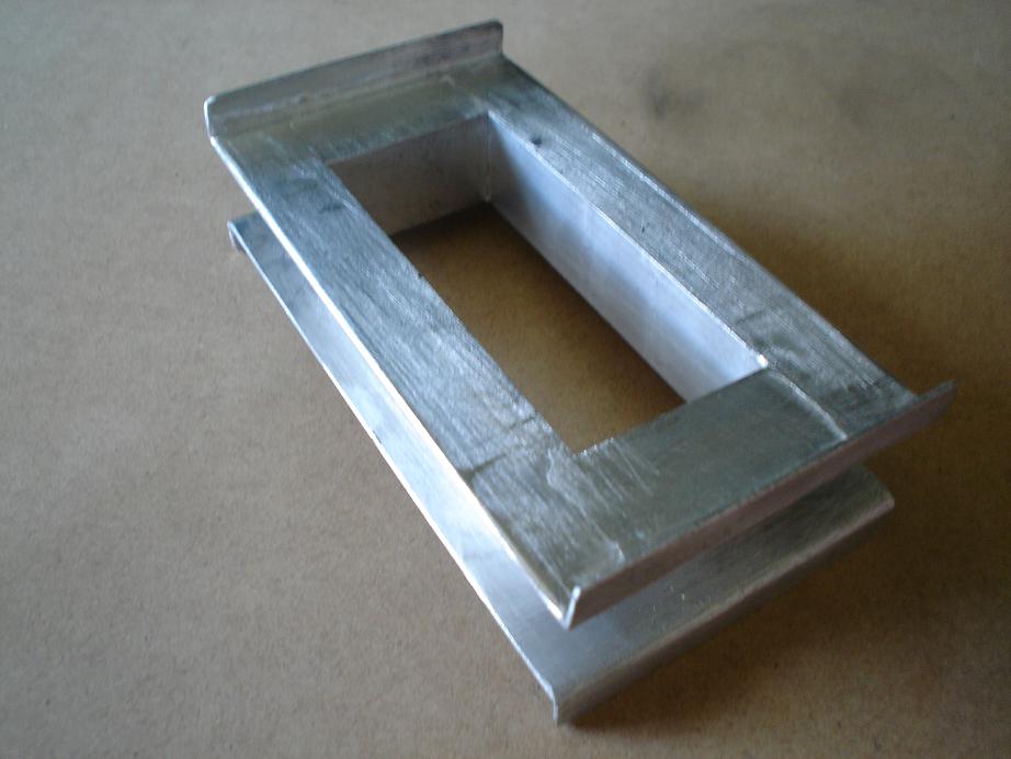
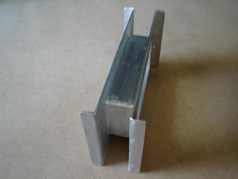
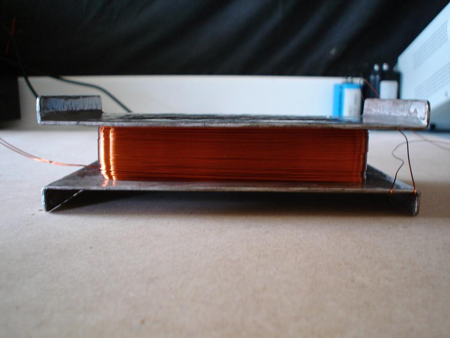
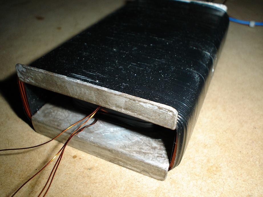
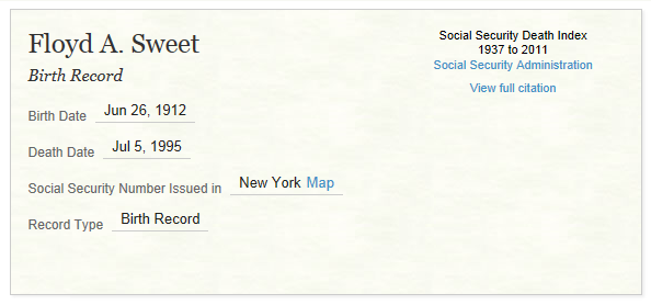
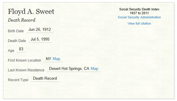
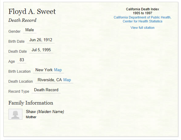
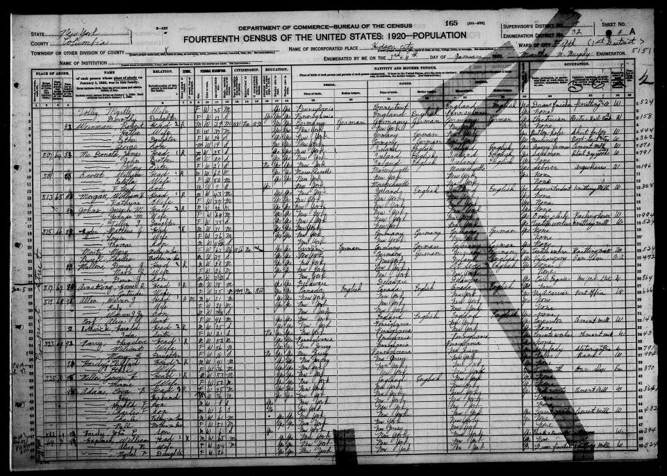
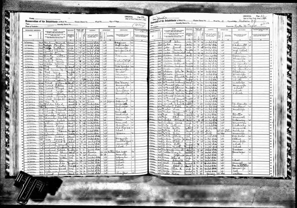
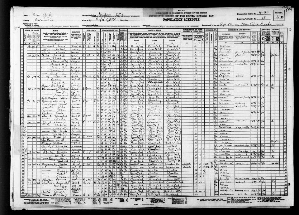

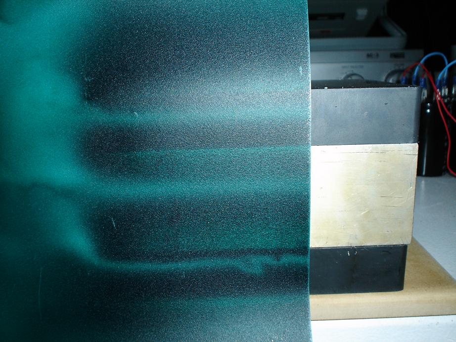


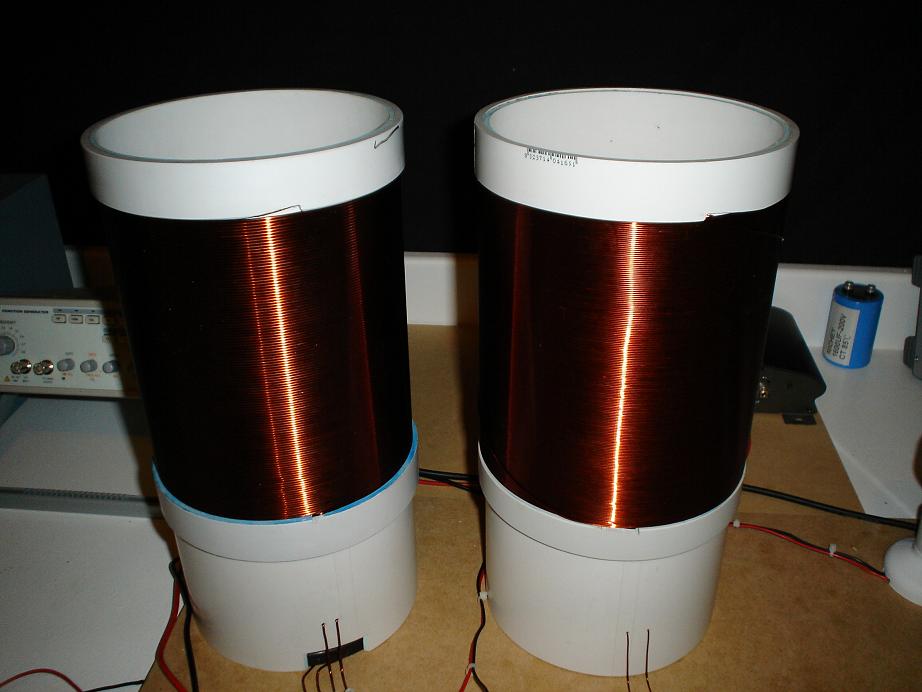
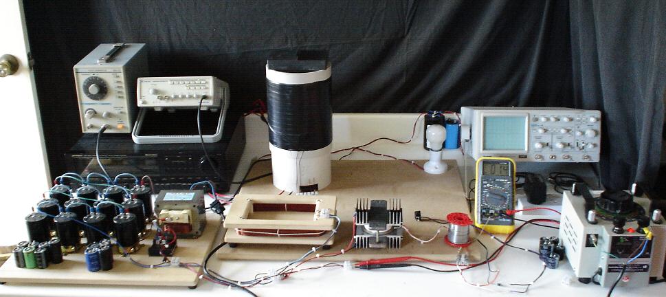
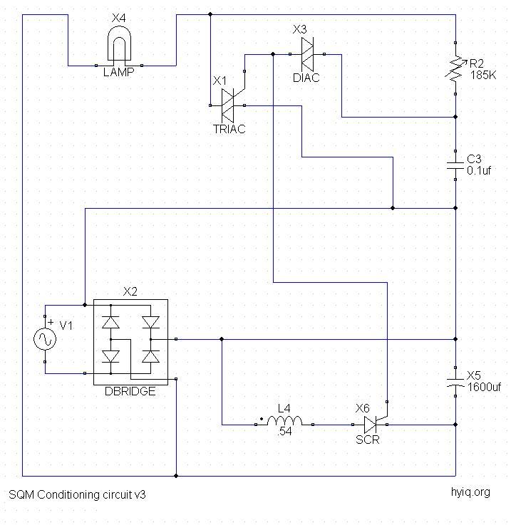
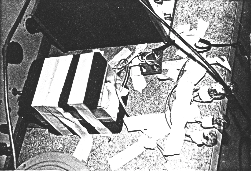
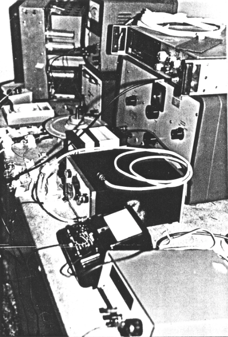
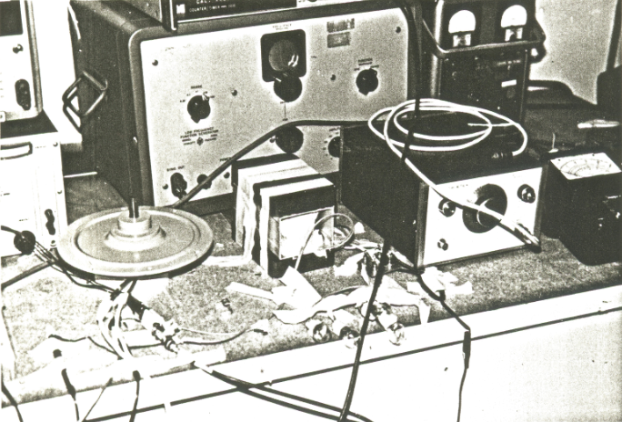
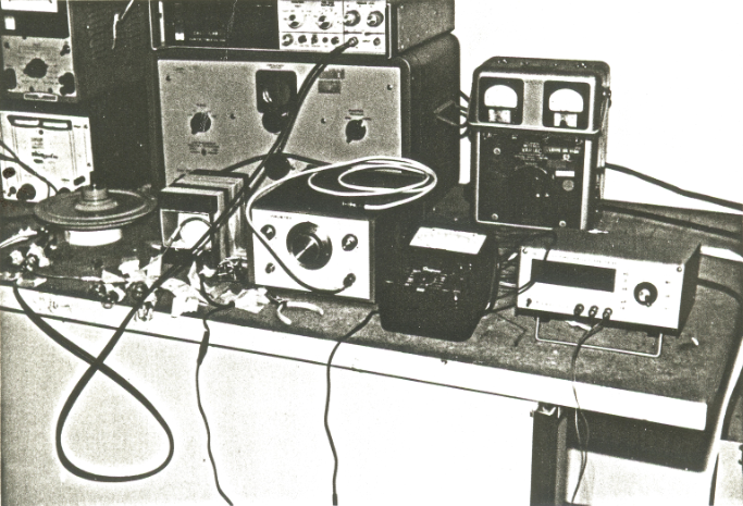
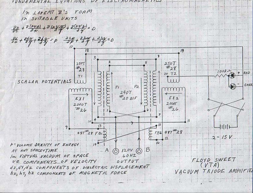
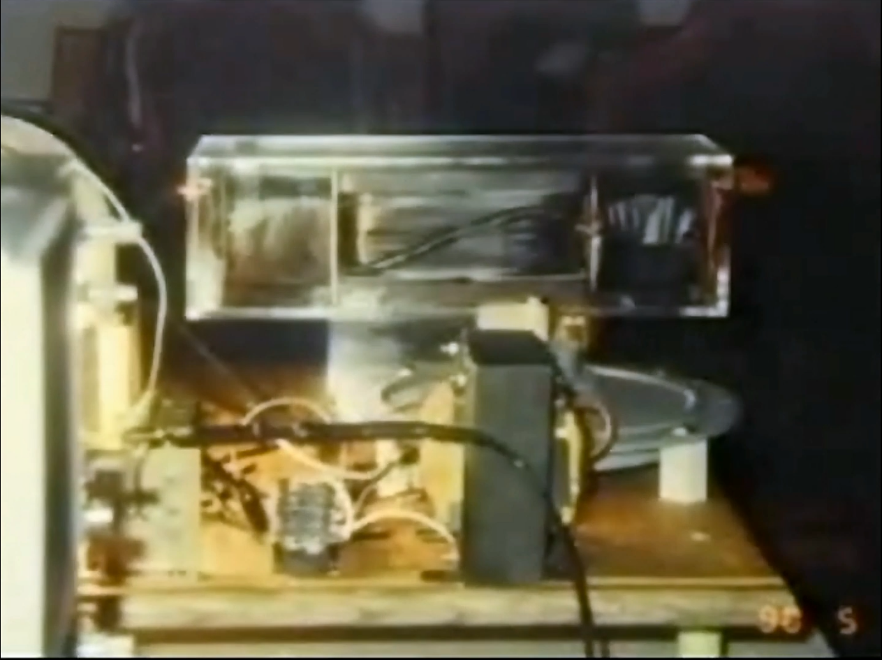
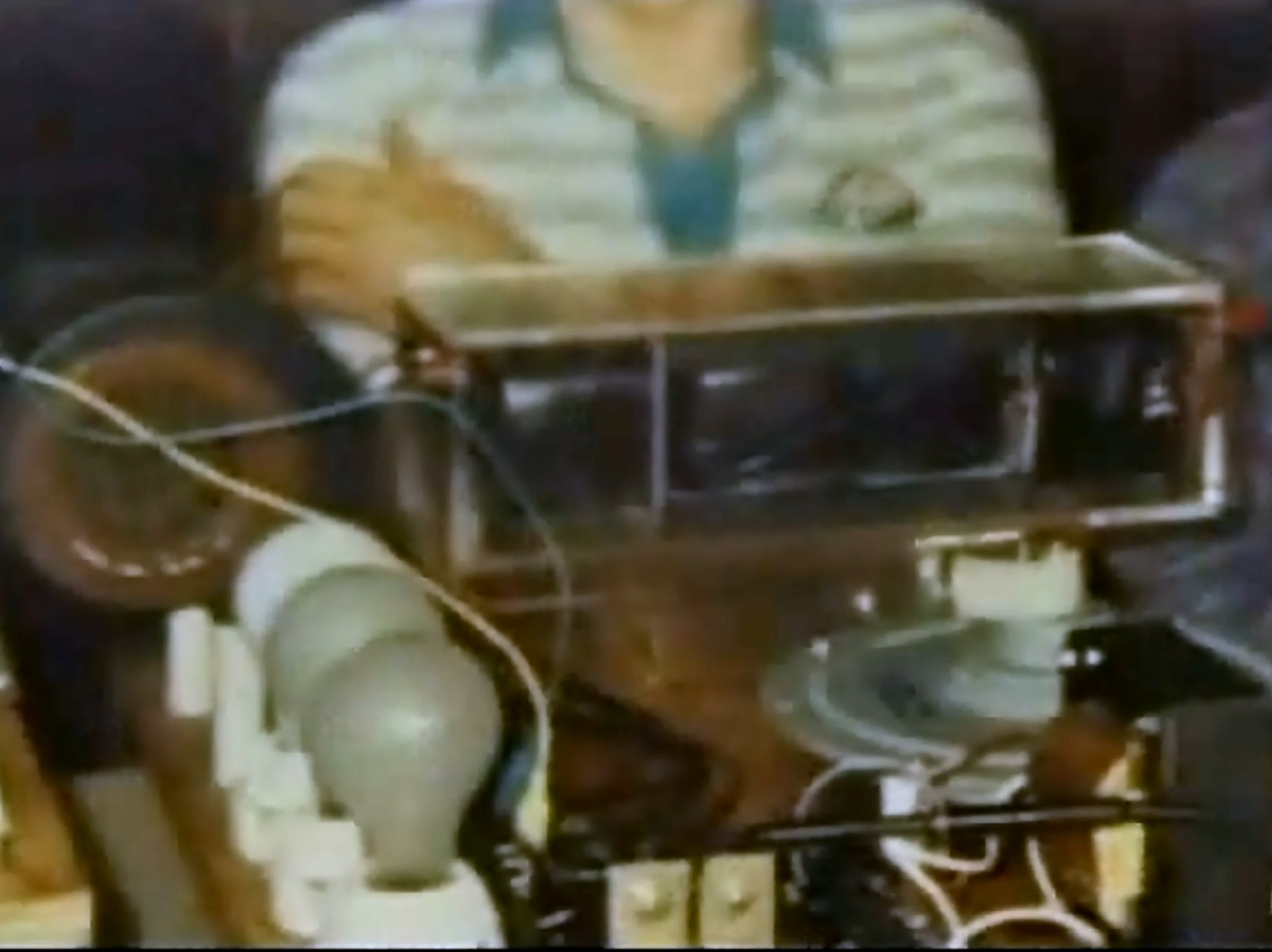
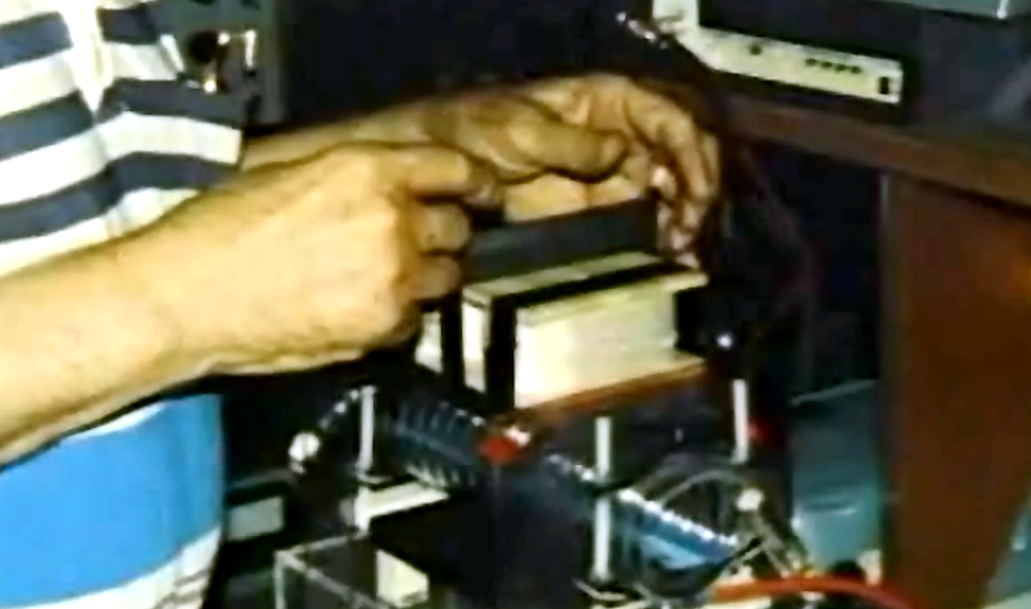
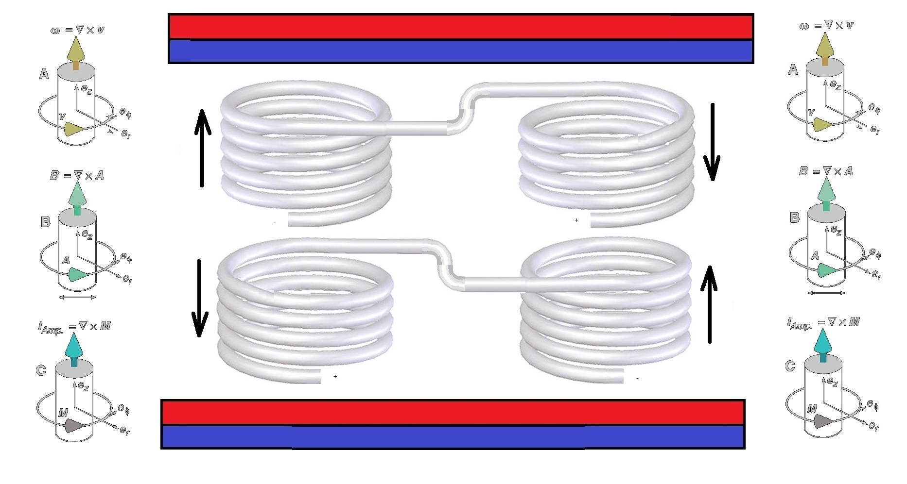
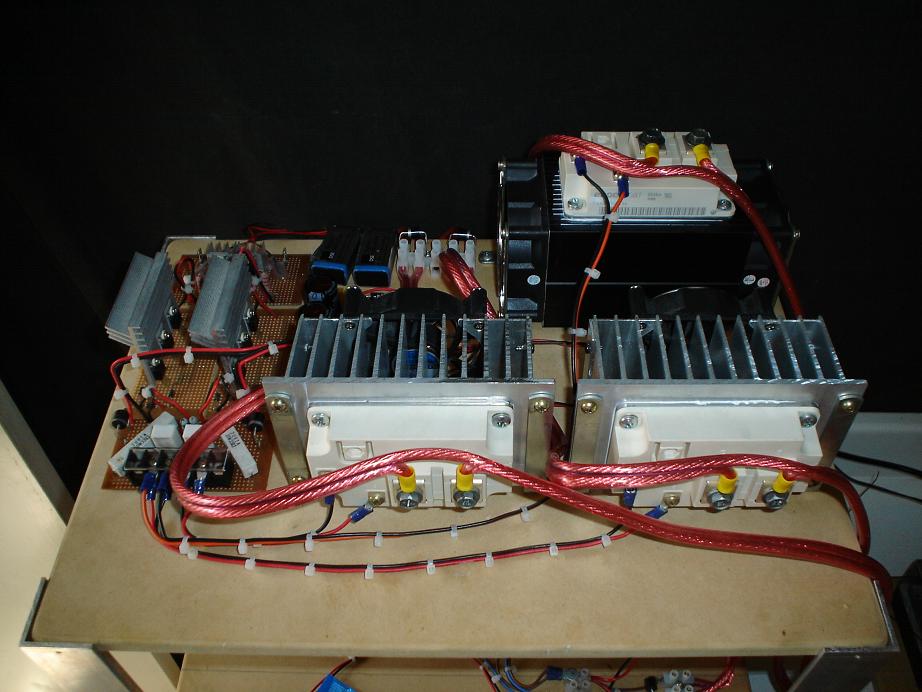
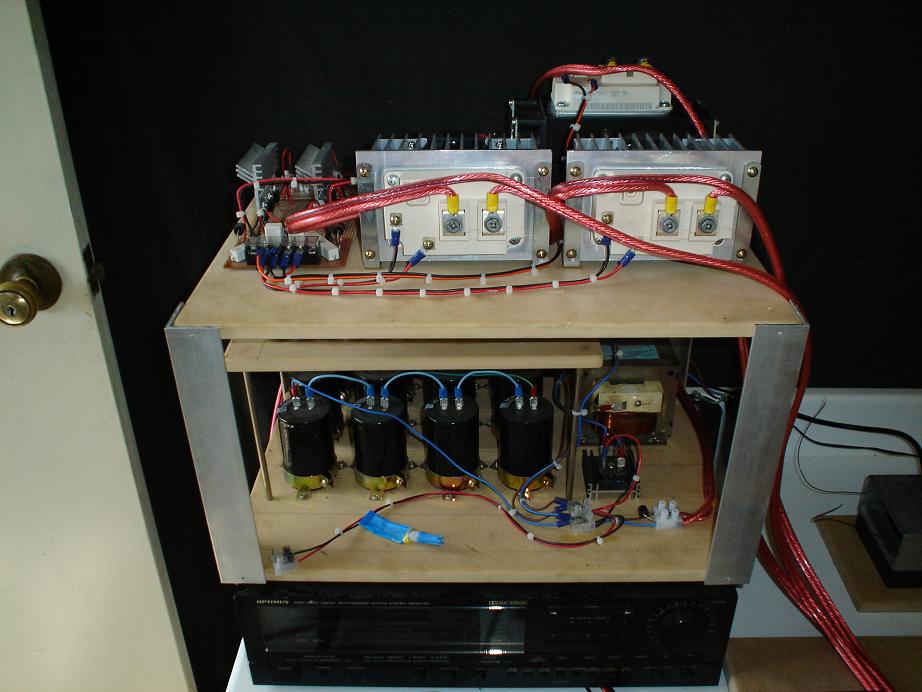
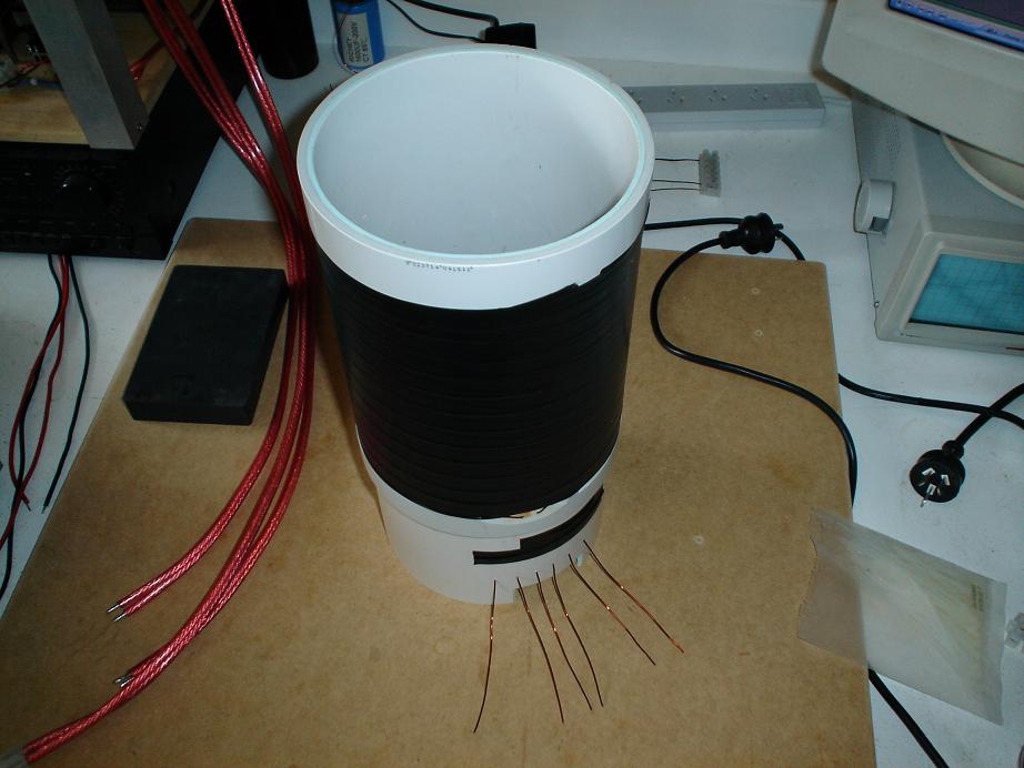
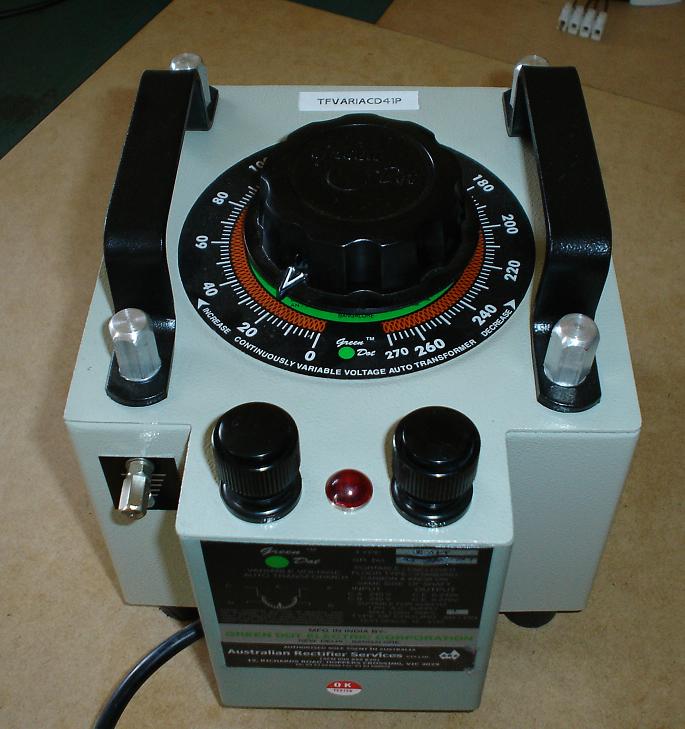
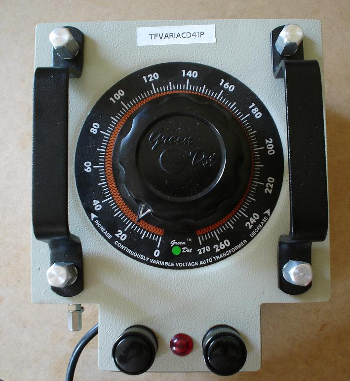
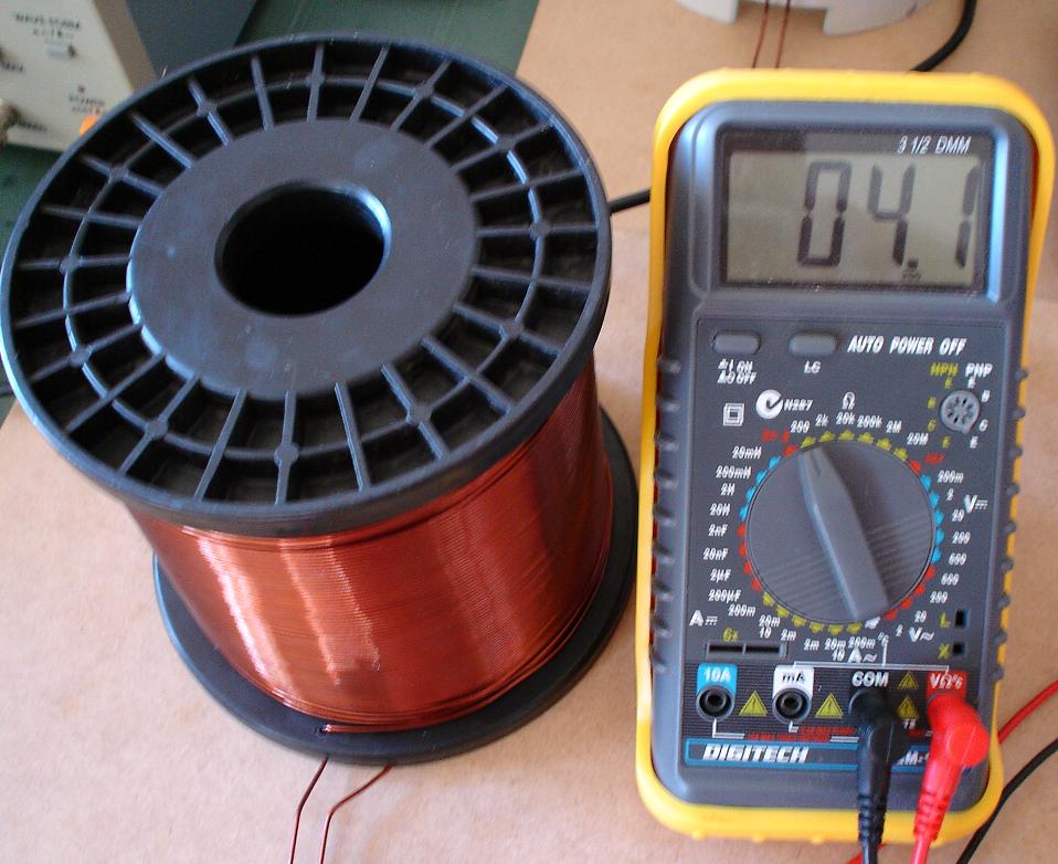
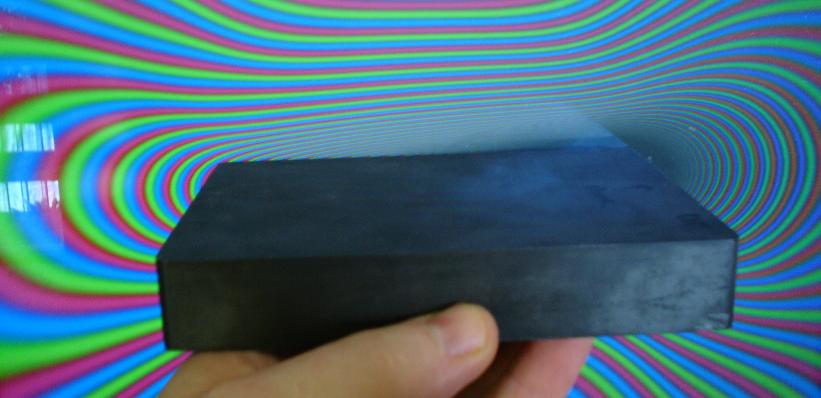
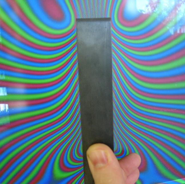
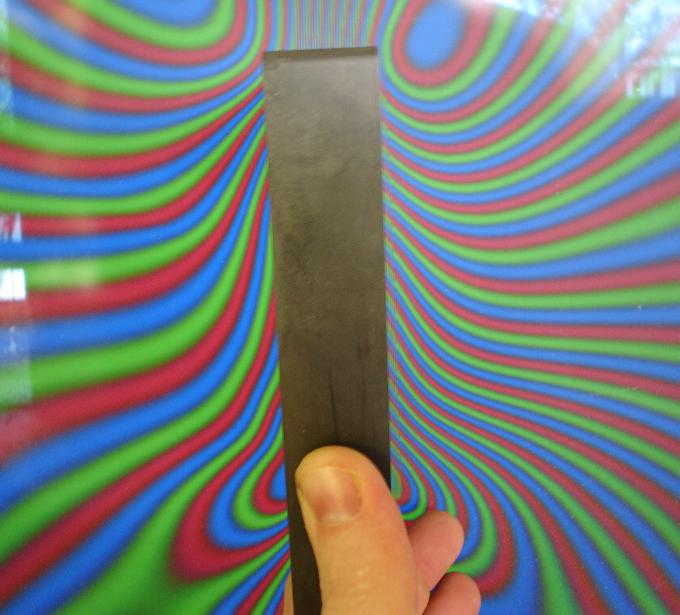
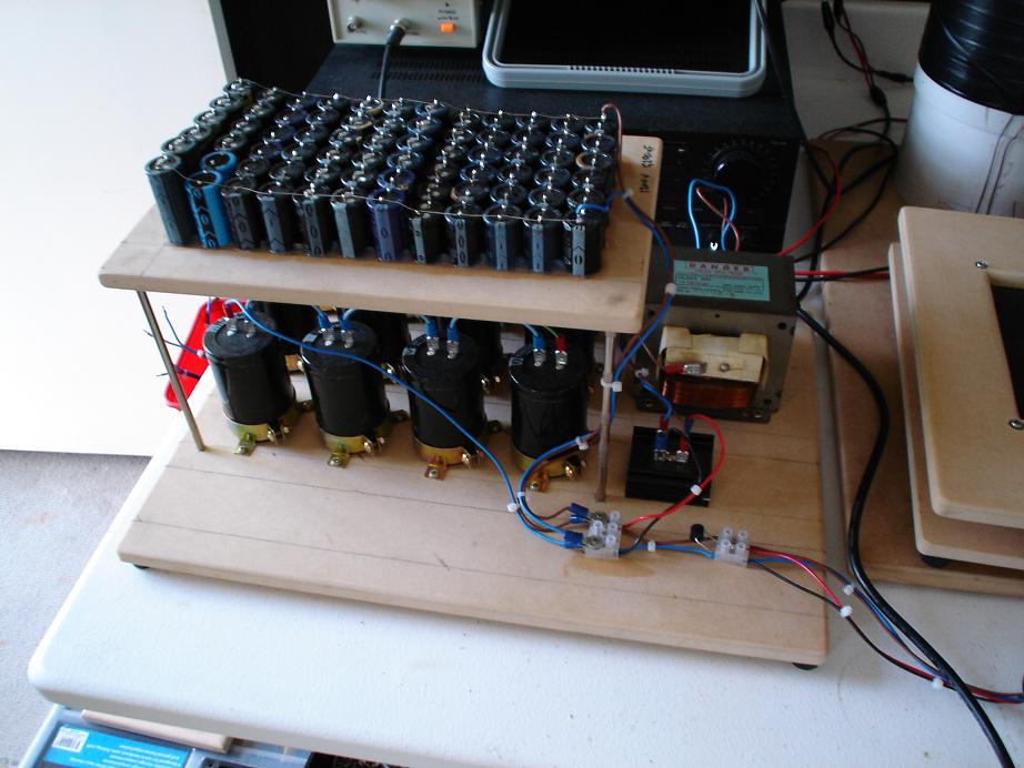
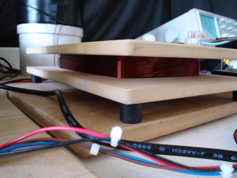
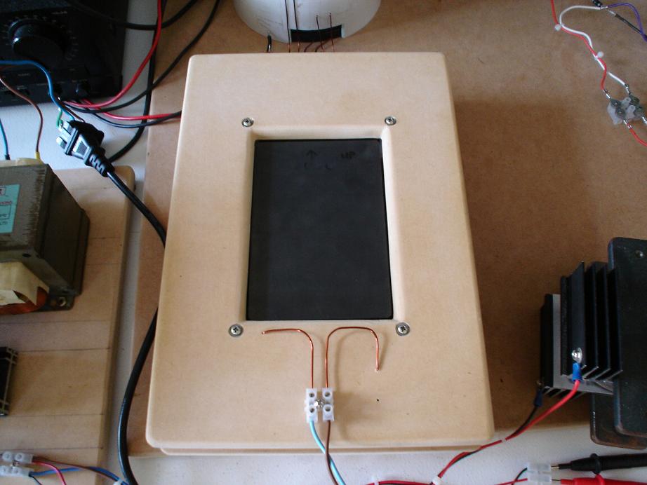
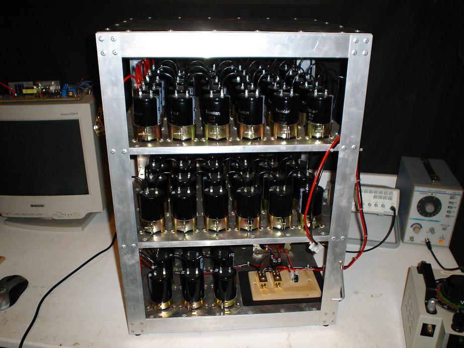
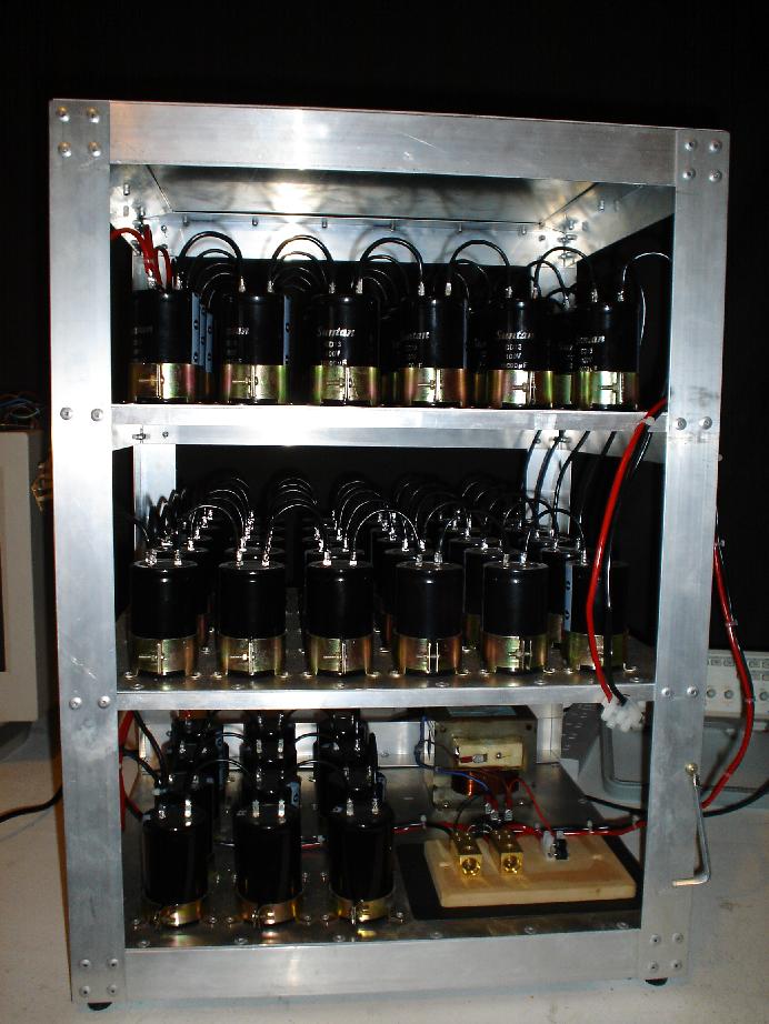
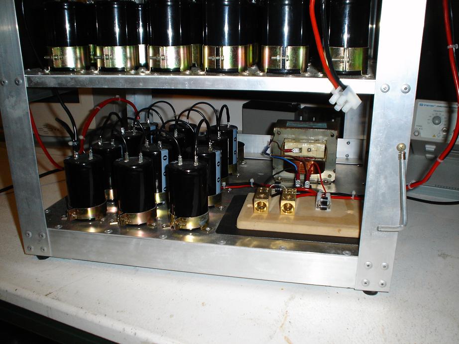
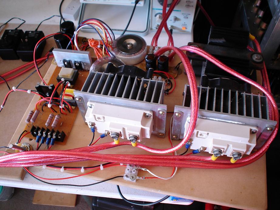
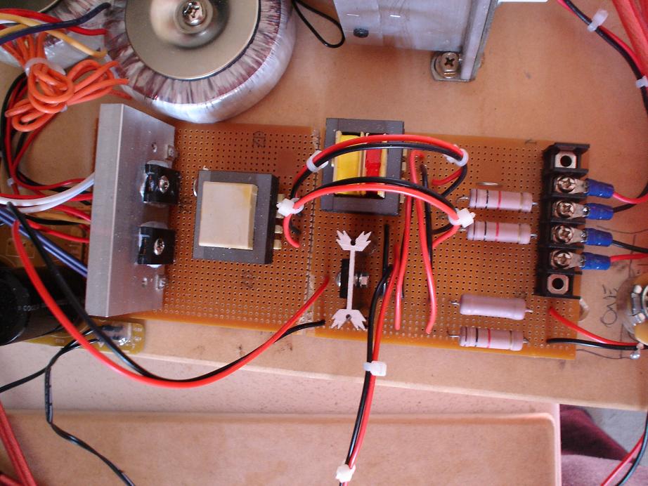
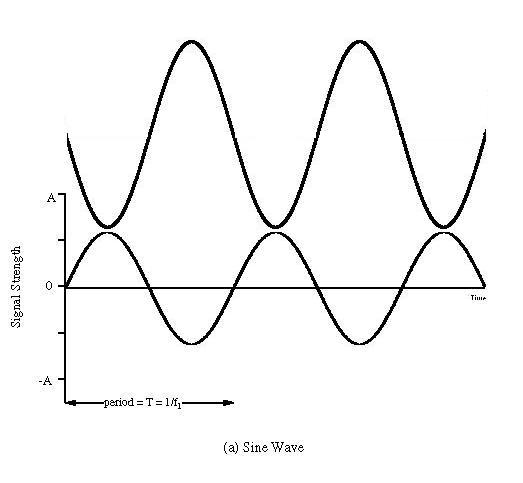
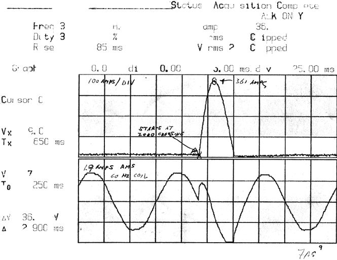
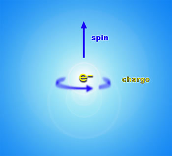
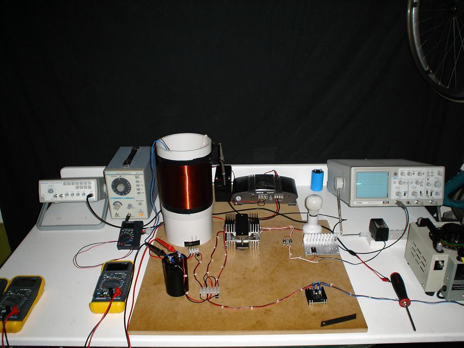
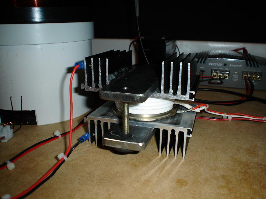
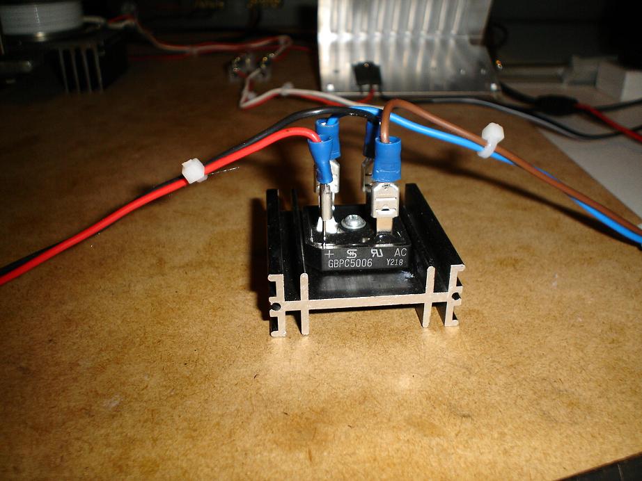
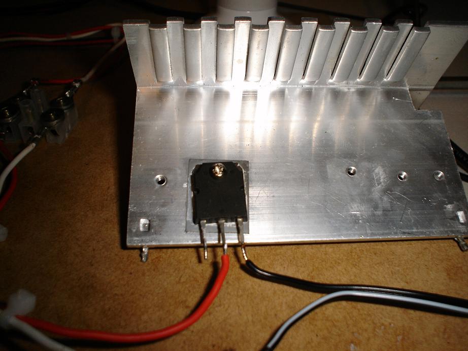
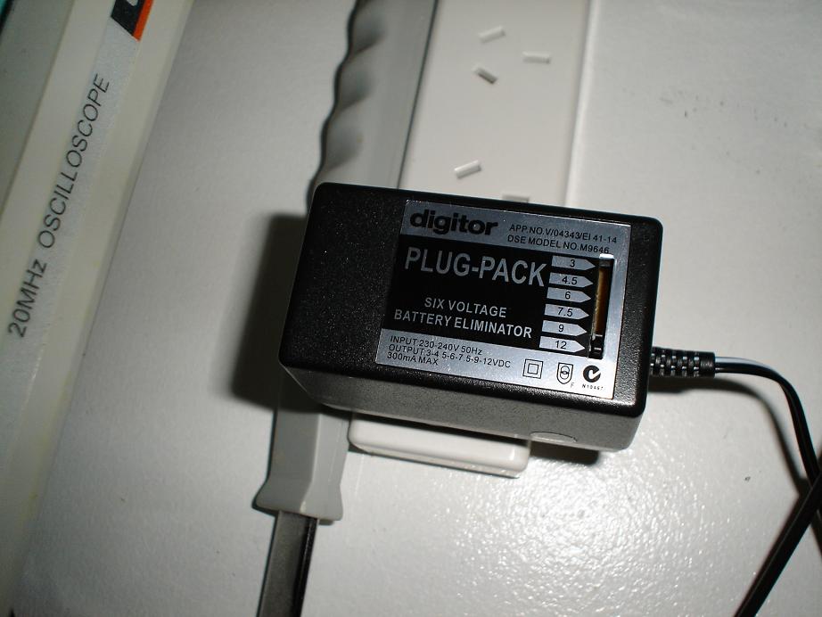
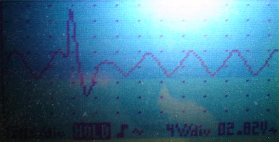
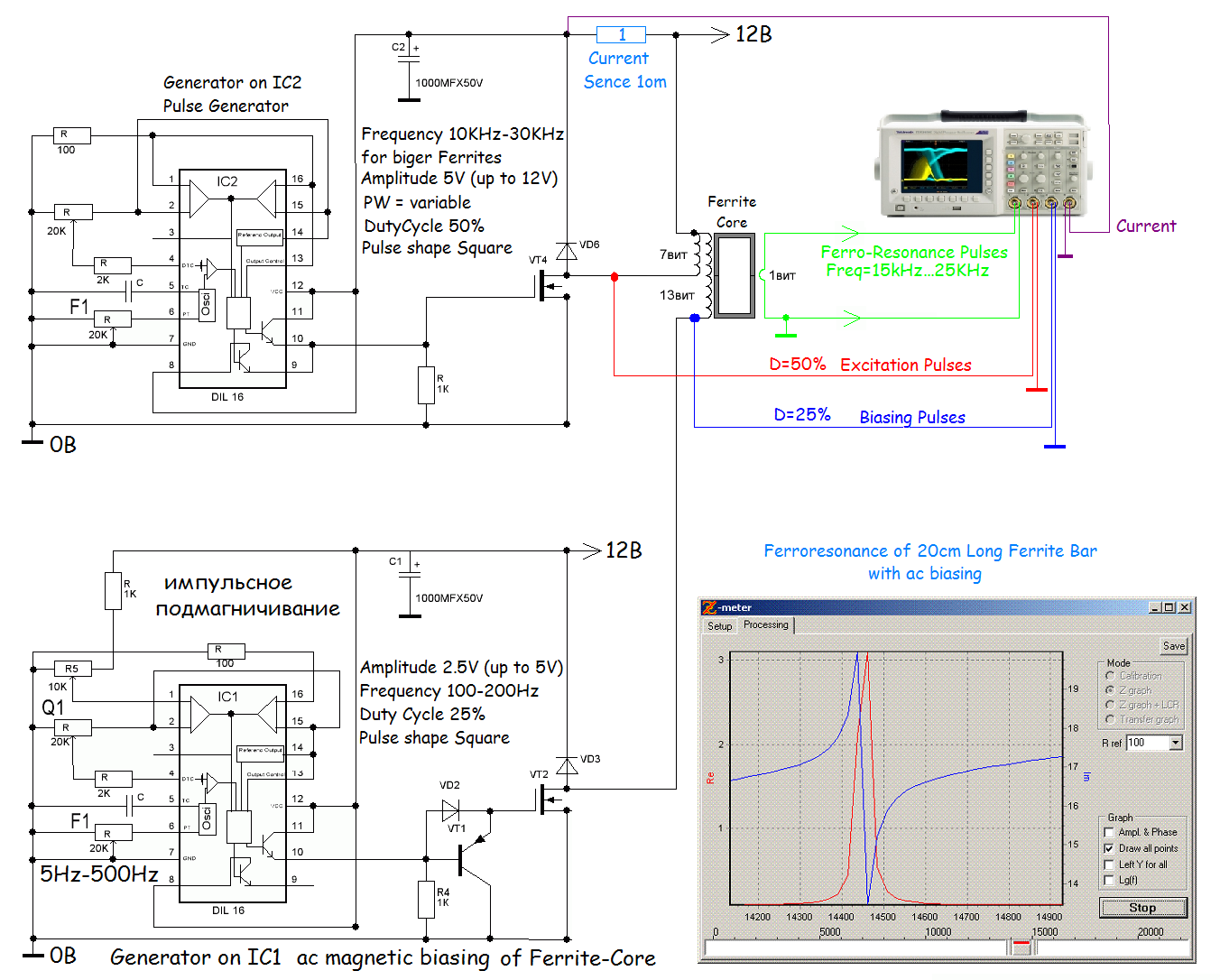
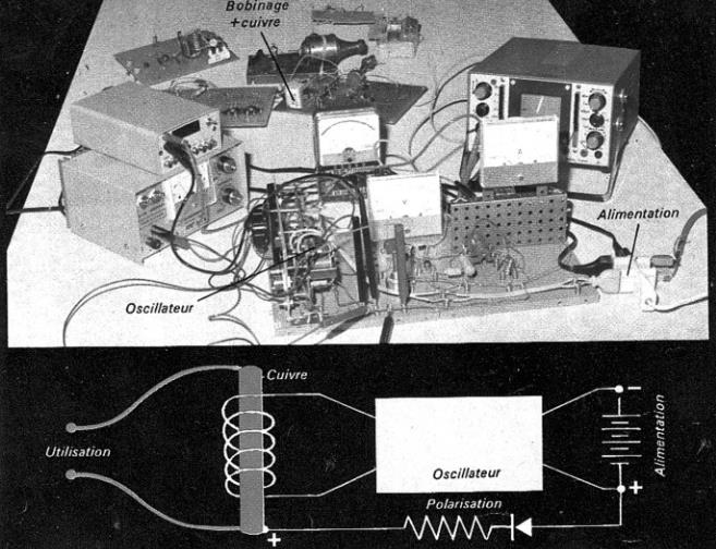
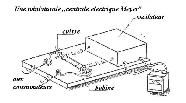
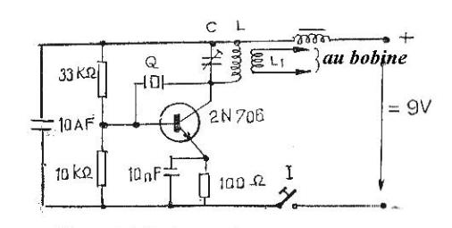
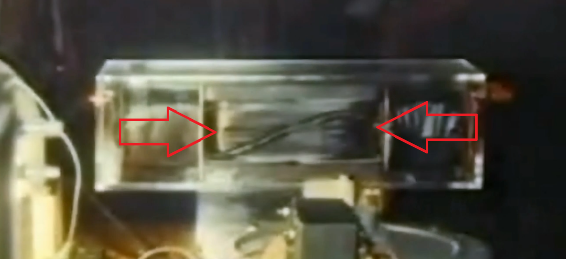
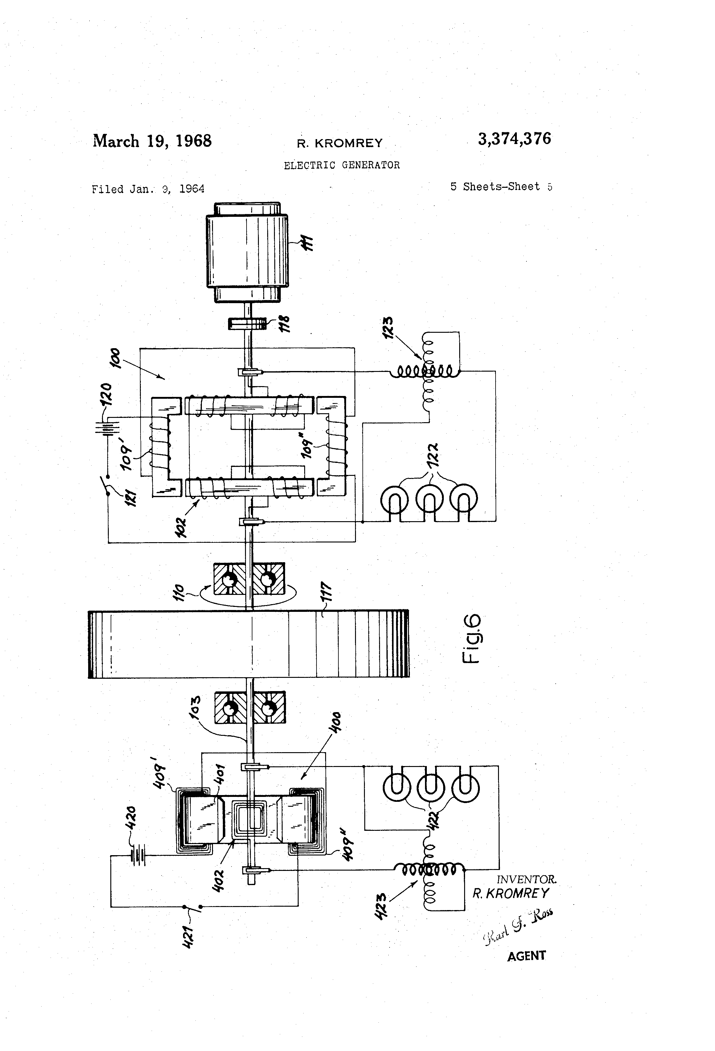
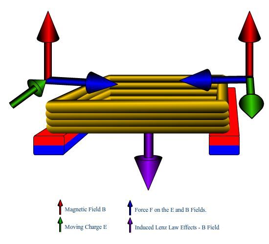


 to µ
to µ .
The aspect ratio of energy current is much like the aspect ratio of space. While
the aspect ratio of space can change, it fundamental velocity
.
The aspect ratio of energy current is much like the aspect ratio of space. While
the aspect ratio of space can change, it fundamental velocity
 cannot really change. This parameter becomes
merely our way of conceptualizing time delay when energy resides in a region of
space.
cannot really change. This parameter becomes
merely our way of conceptualizing time delay when energy resides in a region of
space.
 A /B = Aspect Ratio
  ).
).